Eureka AIR delivers breakthrough ideas for toughest innovation challenges, trusted by R&D personnel around the world.

Path measurement method for a magnetic sensor and sensor

a magnetic sensor and sensor technology, applied in the direction of electric/magnetic measuring arrangements, instruments, measurement devices, etc., can solve the problems of difficult to achieve the effect of ensuring the freedom of play

Active Publication Date: 2019-04-02
METHODE ELECTRONICS MALTA
View PDF20 Cites 6 Cited by
  • Summary
  • Abstract
  • Description
  • Claims
  • Application Information

AI Technical Summary

Benefits of technology

The patent describes a way to achieve a single element with a large inductance, which reduces the number of windings needed. Additionally, it suggests a way to accommodate a measuring object that cannot be easily placed in the correct position or material. This is done by enclosing the object inside a sensor housing and using a spring to ensure continuous contact with the actuating mechanism. The technical effects of these features are a more compact and sealed electronics portion, minimizing interference and noise, and a simplified installation process.

Problems solved by technology

Furthermore, they are complex both in terms of production and application.
Whilst using the sensors in the above cases, they are heavily exposed to moisture, dirt, oils, greases and mechanical stresses.
In practical application, however, the aforementioned eddy current path measurement methods only allow for the detection of distances from the measuring object in the range from 5 mm to 10 mm.
Thus, the possible applications are restricted, because requirements in respect of maximum size are imposed on such sensors depending on the place of installation.
However, this involves an unnecessary restriction of possible uses of the sensor itself.
Since the interaction between the magnetic field and the metal target changes, eddy currents are generated in the metal target, which in turn causes energy loss in the circuit generating a magnetic field.

Method used


Image

  • Path measurement method for a magnetic sensor and sensor
  • Path measurement method for a magnetic sensor and sensor
  • Path measurement method for a magnetic sensor and sensor

Examples


Embodiment Construction

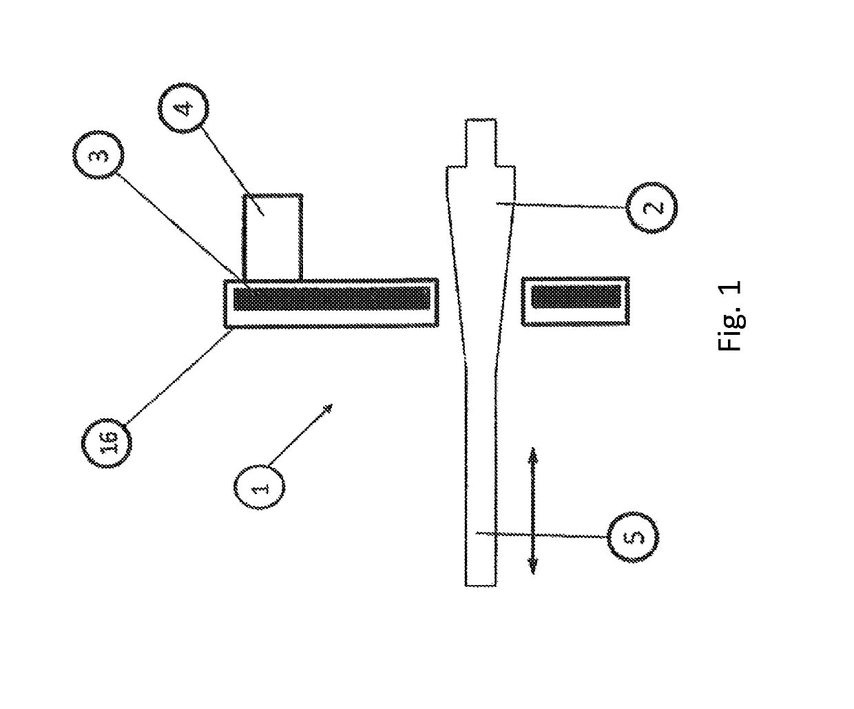
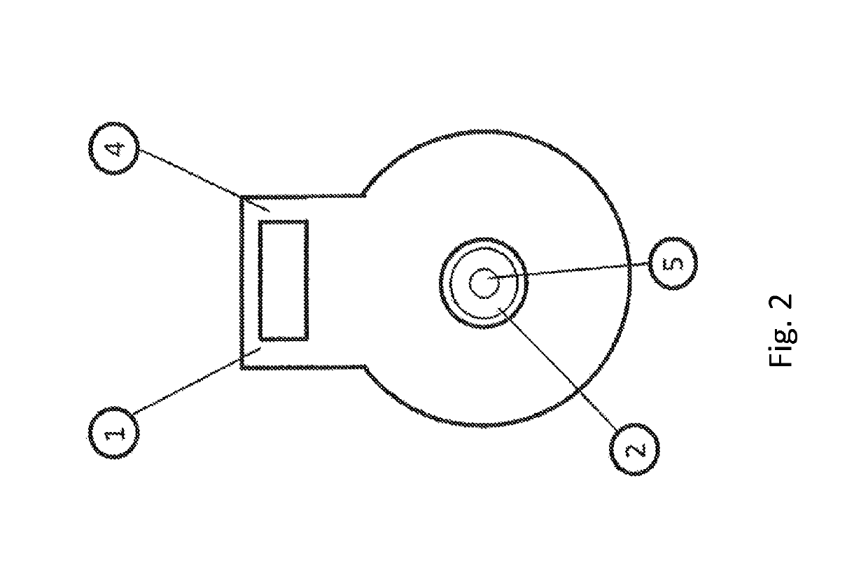
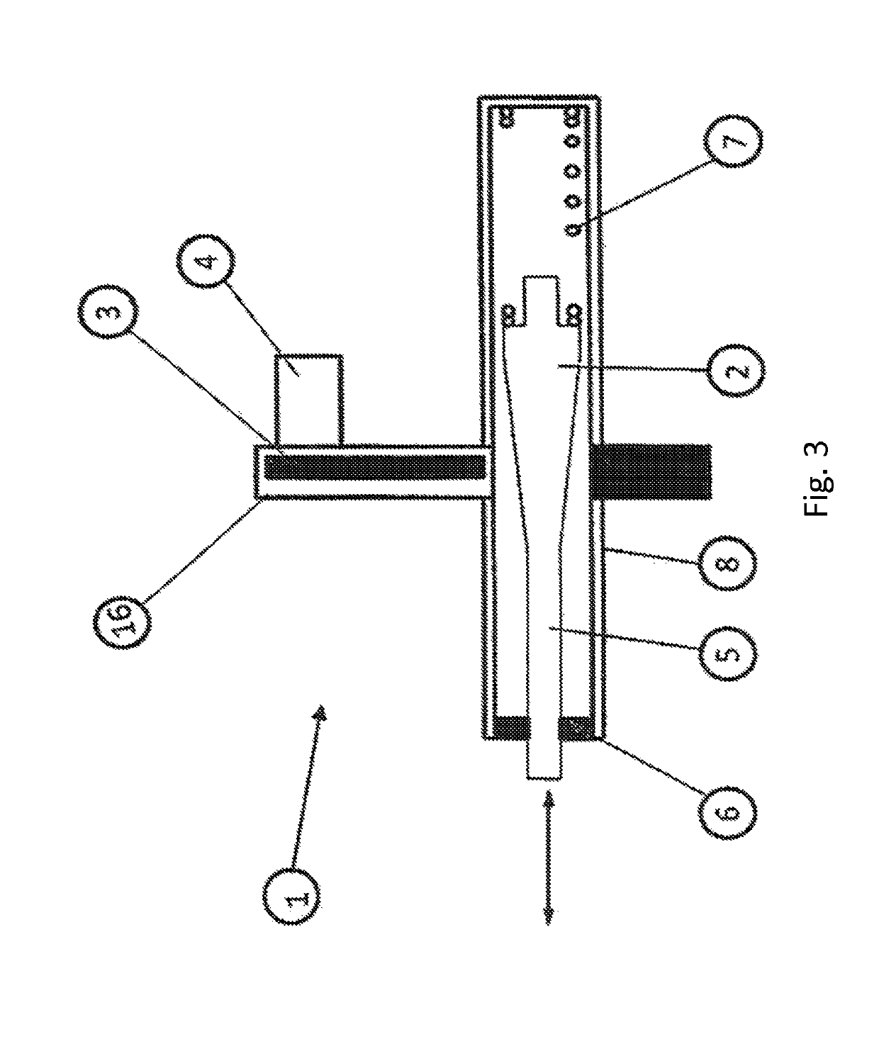
[0120]The path measurement method according to the invention is carried out using a position sensor 1 which cooperates and / or interacts with a measuring object / transducer element 2.

[0121]The sensor consists of at least one electronic unit cooperating with a sensor coil 3, and an electronic connector 4 serving for providing the supply voltage and transmitting signals. The aforementioned components are combined in a common housing 16. The housing 16 can be shaped in the manner customary.

[0122]The mode of operation of the path measurement method consists in activating at first the electronic unit arranged in the sensor by applying an operating voltage. An oscillator 11 existing in the electronic unit excites an oscillation in cooperation with the sensor coil 3, with an oscillation with a specific frequency being generated as a function of the parameters of the oscillator 11 and the sensor coil 3, and the sensor coil 3 establishing a magnetic field.

[0123]A measuring object / transducer el...


PUM


Abstract

A method of path measurement uses eddy current principles and a sensor which interacts with a measuring object. The sensor has an electrical connector and a sensor coil. In accordance with the method, an operating voltage is applied to the sensor such that a magnetic field is built up by an oscillator in cooperation with the sensor coil. A measuring object may be moved in the vicinity of the sensor coil through an opening in the sensor coil to produce field strength changes adjacent to the coil and the oscillator. The field strength changes are detected by an evaluation circuit and transmitted to a microcontroller. The microcontroller processes the signals of the evaluation circuit and provides the evaluation circuit with said signals via an output and protection circuit. The sensor coil consists of a plurality of windings constructed in a planar manner.

Description

RELATED APPLICATION DATA[0001]This application claims the benefit of German patent applications DE 10 2014 218 264.6, filed on Sep. 11, 2014, currently pending, and DE 10 2015 114 205.8 filed on Aug. 26, 2015, currently pending, the disclosures of which are incorporated by reference herein.BACKGROUND AND SUMMARY[0002]The invention relates to a path measurement method for a sensor which cooperates and / or interacts with a measuring object and / or transducer element and which is based on the so-called eddy current principle. The invention further relates to the detection of paths of measuring objects which are disposed in the vicinity of the sensor coil. The sensor and the associated measuring object are moveable relative to one another. The invention further relates to a sensor for path measurement.[0003]Various embodiments of inductively operating sensors for path measurement are known from practice. In particular, contactless path measuring systems are known which provide information...

Claims


Application Information

Patent Timeline
Patent Type & Authority Patents(United States)
IPC IPC(8): G01B7/14G01D5/20G01B7/00
CPCG01B7/003G01D5/2006
Inventor BONNICI, ALLEN CARLZAHRA, STEVE
Owner METHODE ELECTRONICS MALTA
Why Eureka
Eureka Blog
Learn More