Method for controlling resonant converter

Active Publication Date: 2019-04-02
MEANWELL GUANGZHOU ELECTRONICS
View PDF7 Cites 8 Cited by
  • Summary
  • Abstract
  • Description
  • Claims
  • Application Information

AI Technical Summary

Benefits of technology

The present invention provides a method for controlling a resonant converter in a feedback circuit. This method is designed to reduce the sudden drop of output voltage when switching from no-load to full-load operation modes. The method can stabilize the output voltage of the resonant converter even under large variations. Additionally, it allows for a wide-range voltage output and rapid frequency changes in the power switch unit. Integration into conventional feedback circuits enables it to stabilize both the transient and steady-state responses of the resonant converter.

Problems solved by technology

However, enhancement of the hardware not only causes the increase of the whole volume of the resonator unit 24′, but also induces more heat consumption produced under the condition of that resonator unit 24′ fails to efficiently show a good response to the variation of the wide-range operating frequency.
In addition, electronic engineers also know that the LLC resonant converter 2′ with a wide-range voltage output is difficult to be well controlled.
However, in spite of the fact that the proposed method is able to improve the instantaneous drop of the output voltage of the LLC resonant converter 2′ during the switch between the no-load operation mode and the full-load operation mode, this method is also found to induce unstable ripples on the output signal of the LLC resonant converter 2′.
From above descriptions, it is understood that how to design or develop a method for making the LLC resonant converter 2′ provide a wide-range voltage output stably has now become an important issue.

Method used


Image

  • Method for controlling resonant converter
  • Method for controlling resonant converter
  • Method for controlling resonant converter

Examples


Embodiment Construction

[0028]To more clearly describe a method for controlling resonant converter disclosed by the present invention, embodiments of the present invention will be described in detail with reference to the attached drawings hereinafter.

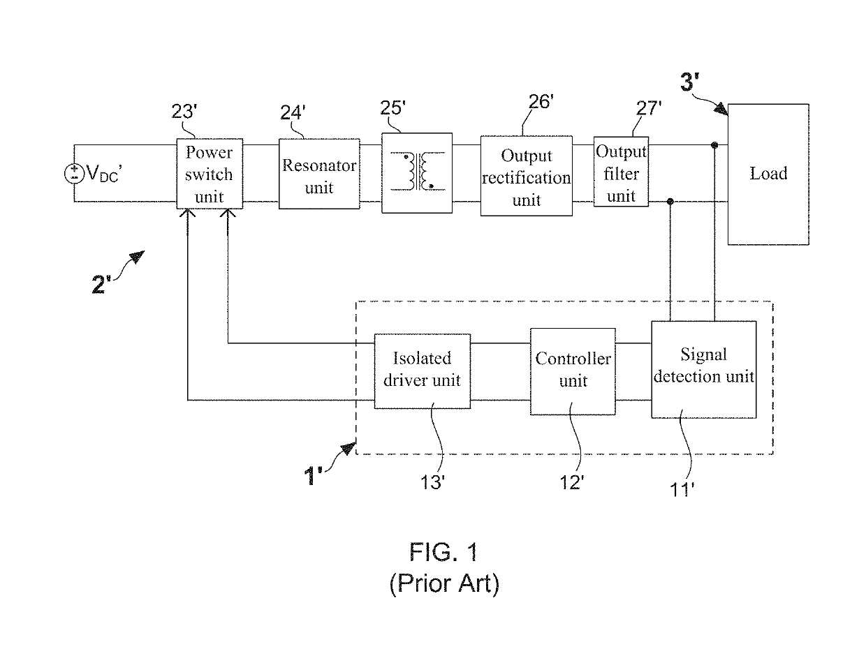
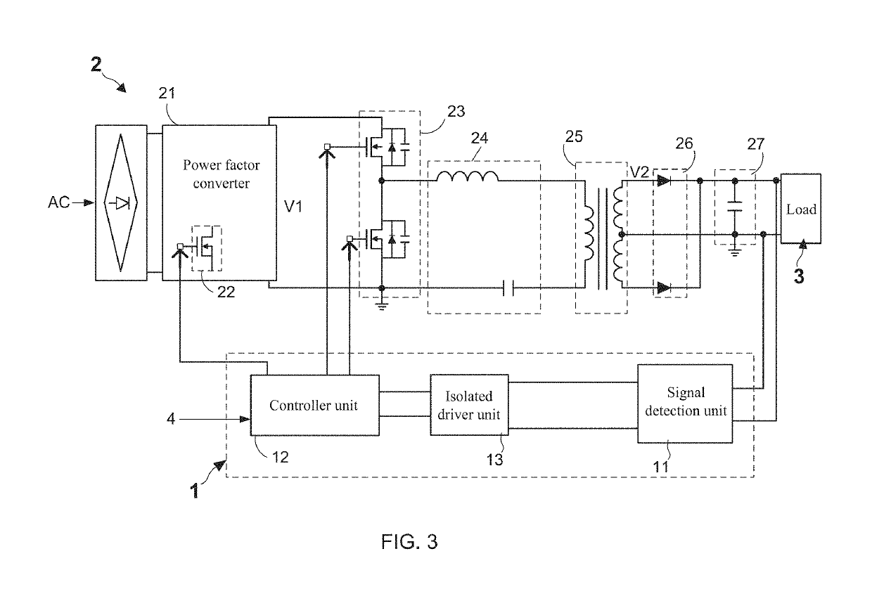
[0029]With reference to FIG. 3, there is provided a circuit framework diagram of a resonant converter applied with a method for controlling resonant converter according to the present invention. As FIG. 3 shows, this resonant converter controlling method is implemented in a controller unit 12 of a feedback circuit 1, wherein the feedback circuit 1 is electrically connected between the resonant converter 2 and a load 3. FIG. 3 also depicts that the resonant converter 2 comprises: a power factor converter 21, a PFC switch unit 22, a power switch unit 23, a resonator unit 24, a transformer unit 25, an output rectification unit 26, and an output filter unit 27. Moreover, the feedback circuit 1 further comprises a signal detection unit 11 and an isolated driver un...


PUM


Abstract

The present invention discloses a method applied in a controller unit of a feedback circuit for controlling a resonant converter. When the operation mode of the resonant converter turns from no load (or light load) to full load (or heave load), the controller unit is configured by the method of the present invention to control a power switch unit in the resonant converter to switch ON and OFF according to an operation frequency of full load (such as 100 KHz), in the case of the fact that an instantaneous drop of the output voltage and a variation of the output current of the resonant converter are over predicted. As a result, the instantaneous drop of the output voltage is largely reduced. Therefore, this method is able to make the resonant converter provide the output voltage stably during the switch between the no-load operation mode and the full-load operation mode.

Description

BACKGROUND OF THE INVENTION1. Field of the Invention[0001]The present invention relates to the technology field of power conversion devices, and more particularly to a method for controlling resonant converter.2. Description of the Prior Art[0002]Technologies of switching-mode power supply (SMPS) have been widely applied in manufacture of power supplies for use in various electrical apparatuses and electronic products. Moreover, since there is a tendency toward developing small-size and light-weight electronic products today, power density of the SMPS needs to be enhanced through raising switching frequency in order to effectively shrink the SMPS's framework volume. Accordingly, LLC resonant converter with advantages of zero voltage switching (ZVS) and zero current switching (ZCS) is hence developed and proposed.[0003]FIG. 1 shows a circuit framework diagram of a conventional LLC resonant converter. As FIG. 1 shows, the conventional LLC resonant converter 2′ comprises: a power switc...

Claims


Application Information

Patent Timeline
IPC IPC(8): H02M3/335H02M1/42H02M1/08H02M7/08
CPCH02M1/4241H02M1/08H02M7/08H02M1/42Y02B70/10Y02P80/10H02M1/0058H02M1/0032H02M3/33571H02M3/01
Inventor CHEN, PO-MINGLU, SHAO-JIE
Owner MEANWELL GUANGZHOU ELECTRONICS
Why Eureka
Try Eureka