Supercharge Your Innovation With Domain-Expert AI Agents!

Distributed customer premises equipment

a customer premises and equipment technology, applied in the field of data routing and forwarding, can solve the problems of high cost and inconvenience, additional cost to the customer or the network operator, function devices, etc., and achieve the effect of improving network management and maximizing field utilization of hardware resources

Active Publication Date: 2019-04-09
CIENA
View PDF31 Cites 3 Cited by
  • Summary
  • Abstract
  • Description
  • Claims
  • Application Information

AI Technical Summary

Benefits of technology

This approach provides improved network management and flexibility, allowing for centralized control of multiple devices, easier configuration, and the ability to upgrade or augment network functions, reducing costs and complexity in managing large-scale networks.

Problems solved by technology

Generally, once the CPE is physically located at the premises of the customer, any changes to the CPE results in a technician visit to the customer, resulting in higher costs and inconvenience.
Furthermore, the CPE usually has to be replaced if a certain functionality or service is not supported by the CPE or if the CPE needs an upgrade resulting in an additional cost to the customer or the network operator.
Furthermore, the CPEs are single function devices and the customer may not be able to enable and use multiple services and functionality using the same CPE.
This makes programming of such routers in a large network (e.g., internet), which may comprise tens of thousands of such routers, complicated and inflexible.
This per router-centric management requirement makes management of such networks very complex and time consuming.
As a result, networks using conventional routers lack the flexibility and dynamic configurability desired by today's (and tomorrow's) network applications such as cloud computing, mobile computing, real-time and on-demand video traffic, and the like.
Therefore, maintaining a network of conventional CPEs, especially CPEs that implement routing capabilities is expensive, complex, inflexible and difficult to upgrade and manage.

Method used


Image

  • Distributed customer premises equipment
  • Distributed customer premises equipment
  • Distributed customer premises equipment

Examples


Embodiment Construction

[0033]In the following description, for the purposes of explanation, specific details are set forth in order to provide a thorough understanding of embodiments of the invention. However, it will be apparent that various embodiments may be practiced without these specific details. The figures and description are not intended to be restrictive. The word “exemplary” is used herein to mean “serving as an example, instance, or illustration.” Any embodiment or design described herein as “exemplary” is not necessarily to be construed as preferred or advantageous over other embodiments or designs.

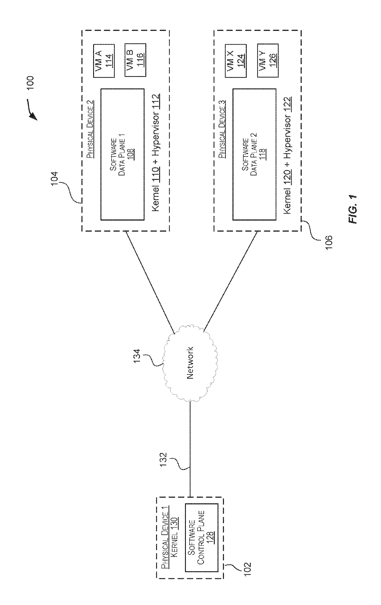
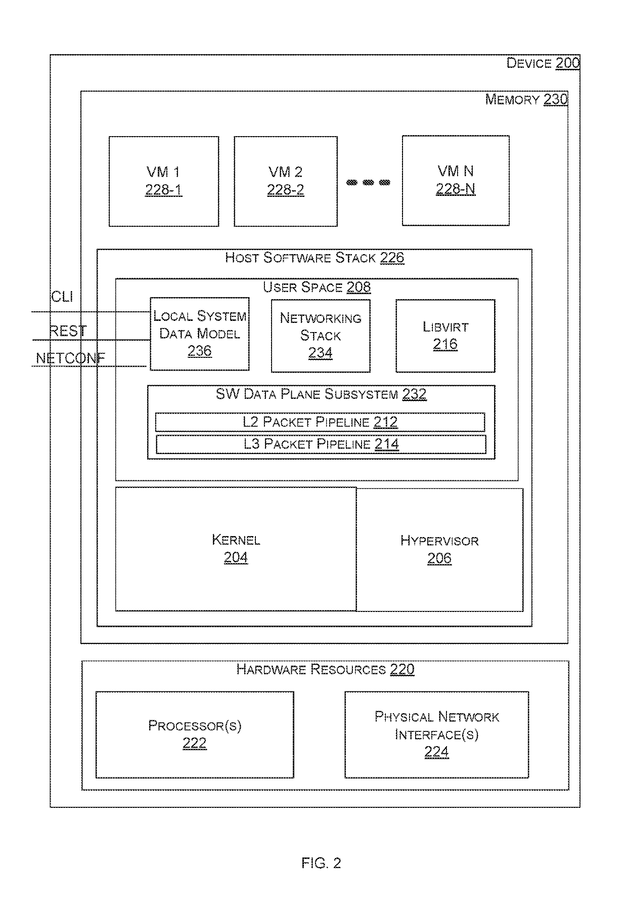
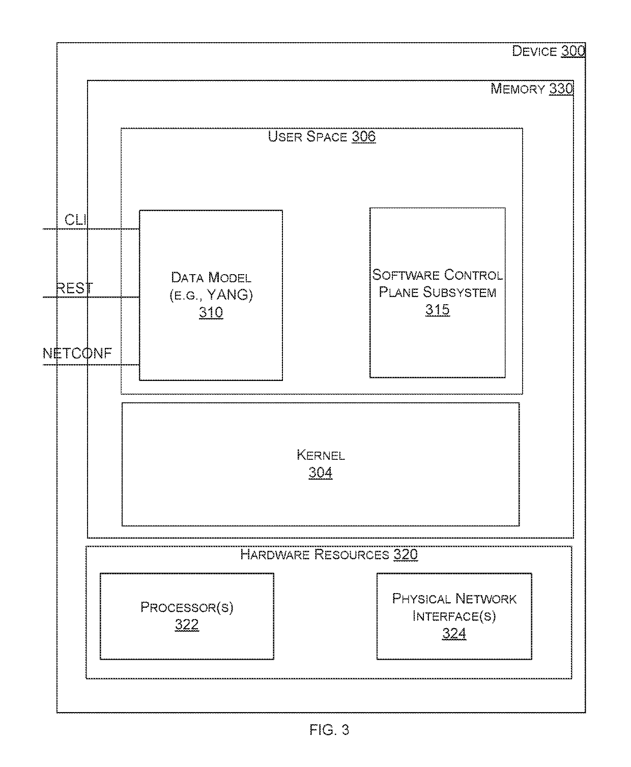
[0034]In certain embodiments, a novel distributed CPE is provided. According to certain embodiments, the distributed CPE includes a centralized control plane server computer and several CPEs executing software data plane subsystems natively (i.e., without virtualization). The control plane server computer executing the control plane subsystem controls the CPEs. Each CPE may also be capable of hosti...


PUM


Abstract

Techniques are disclosed for providing a distributed customer premises equipment (CPE) comprising several devices. The distributed CPE may include a control plane subsystem configured to execute on a first device, a first data plane subsystem configured to execute on a second device, and a second data plane subsystem configured to execute on a third device. The second device may be further configured to execute a first virtual machine capable of executing a first network function. The third device may be further configured to execute a second virtual machine capable of executing a second network function. In certain embodiments, the control plane subsystem may be configured to control forwarding functionality of the first data plane subsystem and the second data plane subsystem, and control the first network function and the second network function. In certain embodiments, the first device and the second device are customer premises equipment (CPE) devices.

Description

CROSS-REFERENCES TO RELATED APPLICATIONS[0001]This patent application claims priority to and is a non-provisional application of U.S. Provisional Patent Application Ser. No. 62 / 385,352, filed Sep. 9, 2016, entitled “DISTRIBUTED CUSTOMER PREMISE EQUIPMENT.” The content of U.S. Provisional Patent Application Ser. No. 62 / 385,352 is incorporated herein by reference in its entirety for all purposes.[0002]This patent application also claims priority to and is a continuation in part of U.S. Non-Provisional patent application Ser. No. 14 / 925,809, filed Oct. 28, 2015, titled “UNIVERSAL CUSTOMER PREMISE EQUIPMENT,” which claims the benefit and priority of U.S. Provisional Application No. 62 / 072,971, filed on Oct. 30, 2014, titled “UNIVERSAL CUSTOMER PREMISE EQUIPMENT,” U.S. Provisional Application No. 62 / 075,175, filed on Nov. 4, 2014, titled “UNIVERSAL CUSTOMER PREMISE EQUIPMENT,” and U.S. Provisional Application No. 62 / 241,059, filed on Oct. 13, 2015, titled “UNIVERSAL CUSTOMER PREMISE EQUI...

Claims


Application Information

Patent Timeline
Patent Type & Authority Patents(United States)
IPC IPC(8): H04L29/08H04L12/713H04L12/931H04L12/741H04L45/74H04L45/586
CPCH04L45/74H04L49/70H04L45/586H04L67/1097
Inventor BAYS, ROBERTNARAYAN, SRINIVAS
Owner CIENA
Features
  • R&D
  • Intellectual Property
  • Life Sciences
  • Materials
  • Tech Scout
  • Unparalleled Data Quality
  • Higher Quality Content
  • 60% Fewer Hallucinations
Learn More