Mother ceramic substrate, ceramic substrate, mother module component, module component, and method of manufacturing mother ceramic substrate

a technology of ceramic substrates and mother ceramics, applied in the direction of printed circuit parts, printed circuit non-printed electrical components association, electrical apparatus contruction details, etc., can solve the problems of serious defects, defective appearance and dimensions of individual ceramic substrates obtained by division, and exposure of inner electrodes, etc., to achieve high form accuracy

Active Publication Date: 2019-04-09
MURATA MFG CO LTD
View PDF13 Cites 1 Cited by
  • Summary
  • Abstract
  • Description
  • Claims
  • Application Information

AI Technical Summary

Benefits of technology

[0041]In the mother ceramic substrate according to the present disclosure, the dividing groove that defines the division position is formed in the principal surface on the one side, and the protruding thread is formed on the principal surface on the other side at the position corresponding to the position of the dividing groove formed in the principal surface on the one side in view in the thickness direction of the mother ceramic substrate. Accordingly, the following advantageous effects are attained.
[0042]At the division along the dividing groove, the division can be performed substantially perpendicularly to the principal surfaces of the mother ceramic substrate.
[0043]When the mother ceramic substrate is divided, a force that curves the mother ceramic substrate is applied so that the dividing groove formed in the principal surface on the one side serves as the start point of break.
[0044]At this time, the stress can be concentrated on a bottom edge of the protruding thread (a mountain portion) formed on the principal surface on the other side. As the result, when the mother ceramic substrate is divided, a crack that advances from the dividing groove in the principal surface on the one side is guided to the bottom edge of the protruding thread (the mountain portion) at the opposite position on the principal surface on the other side.
[0045]Since the protruding thread has a smaller width than the thickness of the mother ceramic substrate, as shown in FIG. 5B, a divided end surface 31a of a mother ceramic substrate 1 (also serving as an end surface of a ceramic substrate after division) divided by extension of a crack C is substantially perpendicular to principal surfaces of the mother ceramic substrate.
[0046]In the mother ceramic substrate according to the present disclosure, since the dividing groove is formed in the principal surface on the one side and the protruding thread is provided on the principal surface on the other side, even if the dividing groove has a depth of about several micrometers, and the protruding thread has a height of several micrometers (that is, without depending on the depth of the dividing groove), the mother ceramic substrate can be assuredly divided (broken) substantially perpendicularly to the principal surfaces of the mother ceramic substrate.

Problems solved by technology

As the result, the appearance and dimensions of individual ceramic substrates obtained by division may be defective.
When the ceramic substrates each are, for example, a multilayer ceramic substrate having an inner electrode, a serious defect such as exposure of the inner electrode may occur.
In contrast, if the depth of the dividing grooves is too large, a trouble such as unintentional break of the ceramic substrate at handling may occur.
Hence it has been difficult to form dividing grooves with a proper depth.
If the depth is too small, the ferrite sheet may not be properly broken along the dividing grooves.

Method used


Image

  • Mother ceramic substrate, ceramic substrate, mother module component, module component, and method of manufacturing mother ceramic substrate
  • Mother ceramic substrate, ceramic substrate, mother module component, module component, and method of manufacturing mother ceramic substrate
  • Mother ceramic substrate, ceramic substrate, mother module component, module component, and method of manufacturing mother ceramic substrate

Examples


first embodiment

[0084]In a first embodiment, a method of manufacturing a ceramic substrate (a ferrite substrate) using magnetic ceramic as a ceramic material is described.

[0085](1) First, magnetic ceramic powder (in this first embodiment, ferrite powder), binder resin, and an organic solvent were mixed, molten, dispersed, then deaerated, and thus ceramic raw material slurry was fabricated.

[0086]Then, the ceramic raw material slurry was formed in a sheet shape by a known method such as a doctor blade method, and dried. Thus, a mother ceramic green sheet with a thickness of 200 μm was fabricated.

[0087]The mother ceramic green sheet may be a multilayer body in which a plurality of ceramic green sheets are laminated.

[0088]Then, the obtained mother ceramic green sheet was cut to have a predetermined size, and hence a cut mother ceramic green sheet, being an unfired mother ceramic substrate according to the present disclosure, was obtained.

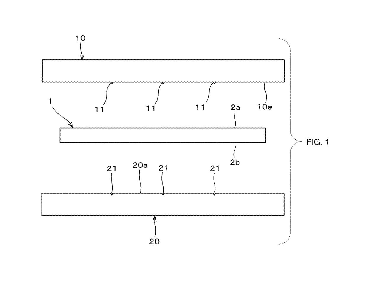
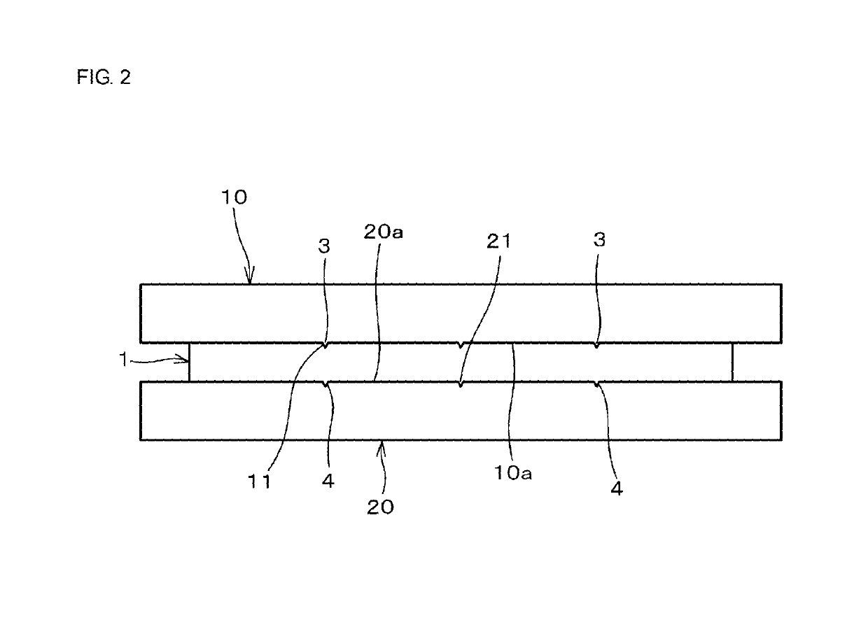
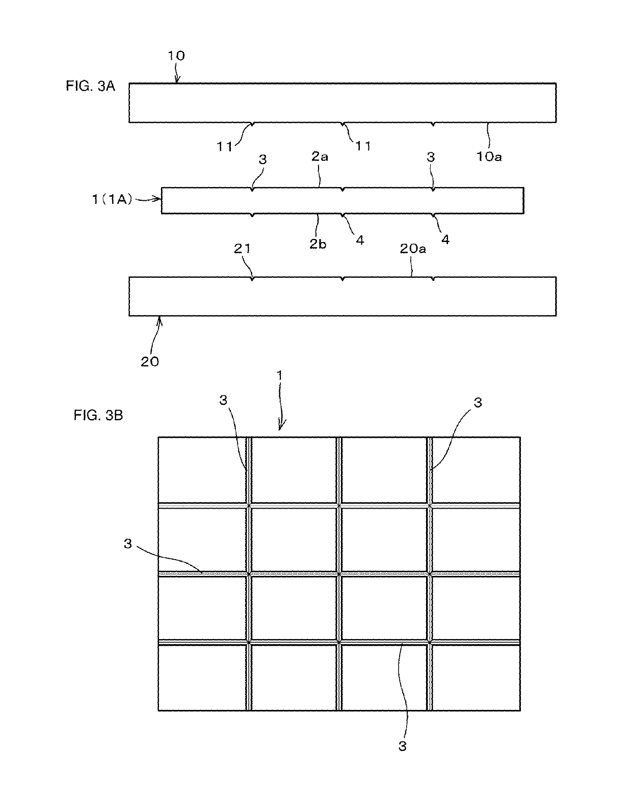
[0089](2) Then, as shown in FIG. 1, a mother ceramic green sheet ...

second embodiment

[0105]In a second embodiment, a method of manufacturing a ceramic substrate (a multilayer ceramic substrate) using low-temperature sintered ceramic as a ceramic material is described.

[0106](1) First, glass ceramic powder (low-temperature sintered ceramic powder), binder resin, and an organic solvent were mixed, molten, dispersed, then deaerated, and thus ceramic raw material slurry was fabricated.

[0107]Then, the ceramic raw material slurry was formed in a sheet shape by a known method such as a doctor blade method, and dried. Thus, a plurality of mother ceramic green sheets each of which has a thickness of 50 μm were fabricated.

[0108]Then, the obtained mother ceramic green sheets were cut to have a predetermined size, a conductive paste (an Ag paste) for forming an inner electrode was applied to each of the mother ceramic green sheets by screen printing, and hence an inner electrode pattern was formed.

[0109]The mother ceramic green sheets may include a via conductor (a kind of inner...

third embodiment

[0115]In a third embodiment, as shown in FIG. 10, a method of manufacturing a module component 150 on which surface mount devices 151 are mounted on a ceramic substrate (a multilayer ceramic substrate) 1 including, for example, a surface conductor, an inner conductor, and a via conductor, is described.

[0116](1) First, a ceramic green sheet (a low-temperature sintered ceramic green sheet) 1 was fabricated by a method similar to that of the second embodiment. Conductive patterns serving as, for example, a surface conductor and an inner conductor were formed and a via hole was formed in the obtained ceramic green sheet 1. The via hole was filled with a conductive material to be a via conductor. Thus, pattern forming sheets 101a each including required conductive patterns 140 were fabricated as shown in FIG. 11.

[0117](2) Then, the pattern forming sheets 101a including the conductive patterns 140 were laminated in a predetermined order (FIG. 12). The obtained multilayer body was put in a...


PUM

PropertyMeasurementUnit
thicknessaaaaaaaaaa
widthaaaaaaaaaa
heightaaaaaaaaaa

Abstract

Provided is a mother ceramic substrate that, when divided into individual substrates (ceramic substrates), can be divided to cause divided end surfaces to be perpendicular to principal surfaces of the individual substrates, and that can provide ceramic substrates with high form accuracy; an individual ceramic substrate obtained from the mother ceramic substrate; a module component including the ceramic substrate; and a method of manufacturing a mother ceramic substrate. In a mother ceramic substrate that can be divided at a predetermined position and separated into a plurality of individual substrates, a dividing groove that defines a division position is formed in a principal surface on one side, and a protruding thread is formed on a principal surface on another side at a position corresponding to a position of the dividing groove formed in the principal surface on the one side in view in a thickness direction of the mother ceramic substrate.

Description

[0001]This is a continuation of International Application No. PCT / JP2015 / 058859 filed on Mar. 24, 2015 which claims priority from Japanese Patent Application No. 2014-109395 filed on May 27, 2014. The contents of these applications are incorporated herein by reference in their entireties.FIELD OF THE DISCLOSURE[0002]The present disclosure relates to a mother ceramic substrate that can be divided at a predetermined position and separated into a plurality of individual substrates, a ceramic substrate obtained by dividing the mother ceramic substrate, a mother module component using the mother ceramic substrate, a module component obtained by dividing the mother module component, and a method of manufacturing a mother ceramic substrate.DESCRIPTION OF THE RELATED ART[0003]To manufacture a ceramic substrate, there has been widely used a method of dividing a fired mother ceramic substrate, and thus dividing the mother ceramic substrate into individual ceramic substrates.[0004]As a method ...

Claims


Application Information

Patent Timeline
Patent Type & Authority Patents(United States)
IPC IPC(8): H05K7/00H05K3/00H05K1/14H05K1/03H05K3/22H05K3/46H05K1/18
CPCH05K1/0306H05K3/0052H05K3/0097H05K3/22H05K1/14H05K2203/1126H05K1/181H05K3/0014H05K3/4629H05K2201/04H05K2201/0909H05K2201/09063H05K2201/09127H05K2203/0108H05K2203/0113H05K1/183H05K3/0044H05K2203/1131
Inventor MAEDA, YUKIOMATSUBARA, MASASHIMATSUBARA, DAIGOKARIYA, MASATOSHI
Owner MURATA MFG CO LTD
Why Eureka
Try Eureka