Check patentability & draft patents in minutes with Patsnap Eureka AI!
Method of coding a real signal into a quantized signal
Active Publication Date: 2019-04-23
COMMISSARIAT A LENERGIE ATOMIQUE ET AUX ENERGIES ALTERNATIVES
View PDF4 Cites 0 Cited by
Summary
Abstract
Description
Claims
Application Information
AI Technical Summary
This helps you quickly interpret patents by identifying the three key elements:
Problems solved by technology
Method used
Benefits of technology
Benefits of technology
The invention is a method for coding a real signal, such as an image or a neural network signal, into a quantized signal. The method involves converting the real sample into a binary or balanced ternary representation, selecting a predetermined number of non-zero bits, and determining the distance between each non-zero bit and its neighbors. The minimum distance between non-zero bits is then coded on a predetermined number of bits. The method can be implemented using a processor or a multiplier circuit. The invention also includes a correspondence table and an exclusive ORlogic gate for efficient multiplication. The technical effect of the invention is to provide a reliable and efficient way to code real signals into quantized signals.
Problems solved by technology
However, the multiplication operation remains complex to implement.
However, the number of bits used to quantize the real numbers is not optimized.
Method used
Image
Click on the blue label to locate the original text in one second.
Reading with bidirectional positioning of images and text.
Examples
first embodiment
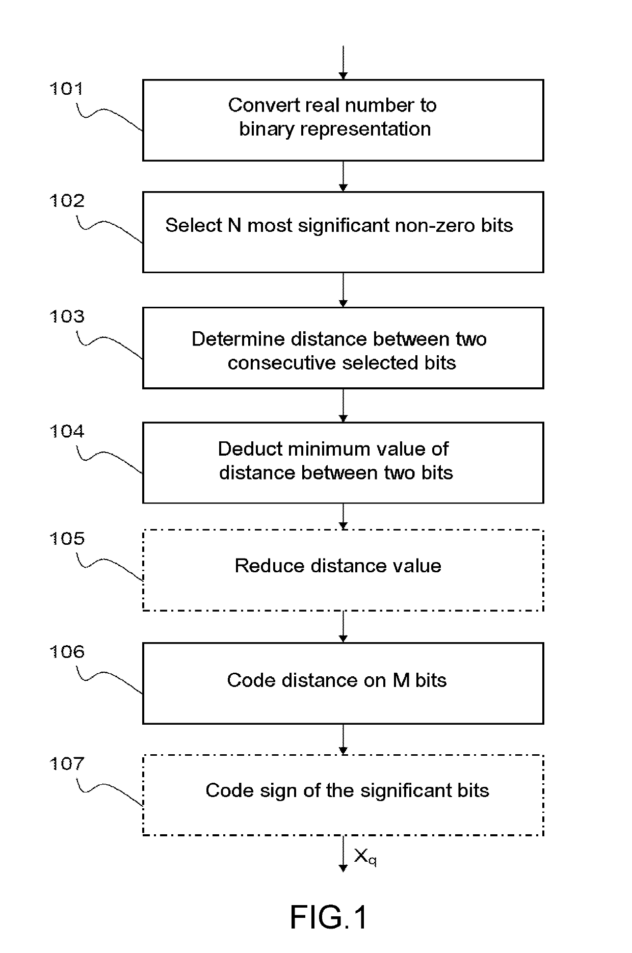
[0041]In a first step 101, the real number Xf to be coded is transformed into a binary representation. In the invention, a binary representation is chosen, stated otherwise a representation to base two. FIG. 2 represents by way of illustration the binary value of the real number 0.158370972 quantized on 16 bits.
[0042]In a second step 102, the N the most significant non-zero bits are selected from the fractional part of the binary representation of the number, and their position is retained. In the example of FIG. 2, N is chosen equal to 3, the number is then truncated, preserving only the three most significant 1-bits, thereby giving the binary value 0.001010001. The positions of these three bits with respect to the decimal point are given by the triplet {3; 5; 9}.
[0043]In a third step 103, the distance between two successive positions is then calculated. In the example of FIG. 2, the distance between the decimal point and the first non-zero bit is equal to 3−0=3, the distance betwe...
second embodiment
[0068]For this reason, and the method according to the invention can also be applied to a signed canonical binary representation or “Canonical Signed Digit” CSD.
[0069]This representation is introduced in reference [3]. It uses a system of ternary numbers {1′,0,1} where 1′ represents the value −1. The CSD representation consists of a sum of signed powers of two just like the signed base two representation. It possesses, however, the following properties which differentiates it from the signed base two representation:[0070]two consecutive bits cannot be non-zero,[0071]the CSD representation is unique,[0072]the CSD representation comprises a minimum number of non-zero bits.
[0073]Thus, in the CSD representation of a number, only one third of the bits are non-zero on average as against a half in a conventional binary representation.
[0074]This property of the CSD representation is advantageous for the invention since an objective of the envisaged method of coding is to code the distances...
PUM
Abstract
A method implemented by a processor for coding a real signal, for example an image signal, into a quantized signal, comprises the following steps applied to each real sample of the real signal: converting the real sample into a digital representation, selecting, in the fractional part of the number, a predetermined number N of most significant non-zero bits, for each non-zero significant bit i selected, i varying from 1 to N, determining its distance Pi with respect to the neighboring selected non-zero significant bit of higher rank or, for the first non-zero significant bit selected, with respect to the decimal point, deducting from the distance Pi the minimum value of distance between two non-zero bits, coding the modified distance Pi on a predetermined number Mi of bits.
Description
CROSS-REFERENCE TO RELATED APPLICATIONS[0001]This application is a National Stage of International patent application PCT / EP2015 / 071939, filed on Sep. 24, 2015, which claims priority to foreign French patent application No. FR 1459470, filed on Oct. 3, 2014, the disclosures of which are incorporated by reference in their entirety.FIELD OF THE INVENTION[0002]The invention relates to the field of applications of signalprocessing and data processing, implemented by software and / or hardware processors with limited calculation resources. The invention relates to all signalprocessing applications which require the execution of multiplication, addition or convolution operations. In particular, the invention envisages real-time applications which require the execution of a large number of operations in a limited time.[0003]The invention pertains more precisely to a method of coding a signal represented in real notation into a quantized signal whose samples are represented in fixed-point n...
Claims
Application Information
Patent Timeline
Application Date:The date an application was filed.
Publication Date:The date a patent or application was officially published.
First Publication Date:The earliest publication date of a patent with the same application number.
Issue Date:Publication date of the patent grant document.
PCT Entry Date:The Entry date of PCT National Phase.
Estimated Expiry Date:The statutory expiry date of a patent right according to the Patent Law, and it is the longest term of protection that the patent right can achieve without the termination of the patent right due to other reasons(Term extension factor has been taken into account ).
Invalid Date:Actual expiry date is based on effective date or publication date of legal transaction data of invalid patent.

