MEMS device, liquid ejecting head, manufacturing method of MEMS device, and manufacturing method of liquid ejecting head

a technology of liquid ejecting head and manufacturing method, which is applied in the direction of printing, inking apparatus, etc., can solve the problems of large volume of mems device and insufficient space between the end of the adhesive and the end of the substra

Active Publication Date: 2019-04-30
SEIKO EPSON CORP
View PDF3 Cites 0 Cited by
  • Summary
  • Abstract
  • Description
  • Claims
  • Application Information

AI Technical Summary

Benefits of technology

[0007]According to the aspect of the invention, the end of the outside of the open hole (that is, end of outside of adhesive) is provided to be with the end of the first substrate and the end of the second substrate, and thus the MEMS device can be miniaturized while securing a sufficient adhesive region.
[0011]According to this configuration, the end of the part deviated from the overlapping part of the main substrate is formed on the outside further than the end of the second substrate, the MEMS device is easily manufactured. That is, when the two mother substrates which are bonded to each other are divided into the individual substrate, division is easily performed. In addition, the end of the overlapping part overlapping with the open hole is provided to be with the end of the second substrate, in a state before being divided from the mother substrate, strength of the overlapping part overlapping with the open hole can be increased. Accordingly, in the overlapping part which is a part in which the strength is likely to be weakened, generation of cracks, clefts, or the like can be suppressed. Further, a thickness of at least a part of the overlapping part is thinner than a thickness of a part deviated from the overlapping part, and thus the two mother substrates which are bonded to each other are further easily divided into an individual substrate.
[0015]According to the manufacturing method, the miniaturized MEMS device can be manufactured. In addition, the adjacent spaces communicate with each other through the process open hole formed on the adhesive, and thus each space can be opened to the outside of the mother substrate through the penetration hole (atmosphere open hole) formed on the outside of a substrate region which becomes either of the first substrate or the second substrate of the mother substrate. As a result, at the time of applying heat to the adhesive, air inside the space can be missed to the outside of the mother substrate. In addition, compared a case in which the penetration hole is provided in each substrate region, deterioration of the strength of the mother substrate can be suppressed.
[0017]According to the manufacturing method, when the two mother substrates which are bonded to each other in the dividing are divided into the individual substrate, the division is easily performed. In addition, in a state before the mother substrate is divided, generation of cracks, clefts, or the like in a region corresponding to the open hole in which the strength is easily weakened can be suppressed.

Problems solved by technology

As a result, a useless space is generated between the end of the adhesive and the end of the substrate, and thus there is a concerned that the MEMS device becomes large as much.

Method used


Image

  • MEMS device, liquid ejecting head, manufacturing method of MEMS device, and manufacturing method of liquid ejecting head
  • MEMS device, liquid ejecting head, manufacturing method of MEMS device, and manufacturing method of liquid ejecting head
  • MEMS device, liquid ejecting head, manufacturing method of MEMS device, and manufacturing method of liquid ejecting head

Examples


Embodiment Construction

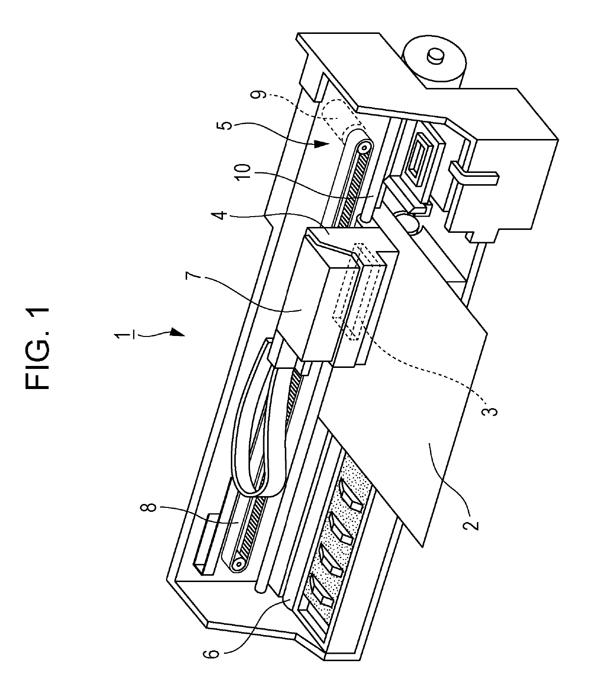
[0033]Hereinafter, embodiments for carrying out the invention will be described with reference to attached drawings. Also, various limitations are made as a preferred specific example of the invention in the embodiments to be described later, but a scope of the invention is not limited to aspects thereof unless particularly there is no disclosure which intends to limit the invention in description to be described later. In addition, hereinafter, a liquid ejecting head which is in one category of the MEMS device, particularly, an ink jet type recording head (hereinafter, recording head) 3 which is a type of the liquid ejecting head will be exemplified. FIG. 1 is a schematic view of an ink jet type printer (hereinafter, printer) 1 which is a type of a liquid ejecting apparatus mounted in the recording head 3.

[0034]The printer 1 is a device which records an image, or the like by ejecting ink (a type of liquid) to a surface of a recording medium 2 (a type of object to which the ink is l...


PUM


Abstract

There is provided an MEMS device in which a first substrate provided with a driving element and a second substrate protecting the driving element are bonded to each other with an adhesive, in which the driving element is formed inside the space surrounded by the adhesive between the first substrate and the second substrate, an open hole which communicates with the space and the outside of the adhesive is formed on the adhesive, and an end of the outside of the open hole is provided to be with an end of the first substrate and an end of the second substrate.

Description

BACKGROUND1. Technical Field[0001]The entire disclosure of Japanese Patent Application No: 2016-127301, filed Jun. 28, 2016 is expressly incorporated by reference herein in its entirety.[0002]The present invention relates to an MEMS device including a structure in which two substrates are bonded to each other using an adhesive, a liquid ejecting head, a manufacturing method of the MEMS device, and a manufacturing method of the liquid ejecting head.2. Related Art[0003]As a micro electro mechanical systems (MEMS) device being applied to a liquid ejecting head, or the like, a device in which two substrates are bonded to each other using an adhesive with a gap therebetween is used. A space surrounded by the adhesive is formed between two substrates of the MEMS device. Also, a driving element such as a piezoelectric element is formed inside the space. As such a manufacturing method of the MEMS device, a method of dividing two mother substrates in which a plurality of regions which respec...

Claims


Application Information

Patent Timeline
Patent Type & Authority Patents(United States)
IPC IPC(8): B41J2/16B41J2/14
CPCB41J2/1623B41J2/14233B41J2/161B41J2/1607B41J2/1626B41J2/1629B41J2/1634B41J2/1643B41J2/1631B41J2202/18B41J2/1645B41J2002/14241B41J2002/14491B41J2202/11
Inventor NAGANUMA, YOICHITANAKA, SHUICHIHIRAI, EIJUHAMAGUCHI, TOSHIAKI
Owner SEIKO EPSON CORP
Why Eureka
Try Eureka