Work vehicle

a technology for working vehicles and vehicles, applied in the direction of braking systems, jet propulsion mountings, gearing, etc., can solve the problems of long and complex hydraulic systems between the hydraulic pressure source and the hydraulic devices, affecting the service life of the hydraulic system, and requiring cumbersome maintenance work, so as to reduce the number of dirty or damaged double speed valves and the effect of reducing the number of damage to the double speed valve and the four-wheel drive valv

Active Publication Date: 2019-04-30
YANMAR POWER TECHNOLOGY CO LTD
View PDF14 Cites 4 Cited by
  • Summary
  • Abstract
  • Description
  • Claims
  • Application Information

AI Technical Summary

Benefits of technology

[0022]According to the embodiment of the present invention, a work vehicle includes: an engine installed in a traveling machine body supported by a traveling unit; and a transmission case incorporating a hydraulic continuously variable transmission configured to shift driving force from the engine. The transmission case incorporates a forward / backward traveling switching mechanism configured to switch an output from the hydraulic continuously variable transmission between normal rotation and reverse rotation directions. The engine is installed in a front portion of a frame member forming the traveling machine body. The transmission case is coupled to a rear portion of the frame member. The engine and the transmission case are coupled to each other in a driving-force transmittable manner via a driving force transmission shaft. The work vehicle further includes: a forward traveling valve for a forward traveling hydraulic clutch configured to enable and disable a normal rotation output transmitted toward the traveling unit; a backward traveling valve for a backward traveling hydraulic clutch configured to enable and disable a reverse rotation output transmitted toward the traveling unit; and a master valve configured to control hydraulic oil supplying to the forward traveling valve and the backward traveling valve. A part of a hydraulic circuit establishing connection between the hydraulic pressure source and the hydraulic clutches is formed on a front lid member that is detachably attached to close a front surface opening of the transmission case. The forward traveling valve, the backward traveling valve, and the master valve are attached on a front surface side of the front lid member. Thus, the forward traveling valve, the backward traveling valve, and the master valve can be disposed with a dead space between the engine and the transmission case effectively utilized, whereby space saving can be achieved.
[0031]A work vehicle according to the embodiment of the present invention, the transmission case is divided into three sections including a front case, an intermediate case, and a rear case. The PTO hydraulic clutch and the PTO transmission mechanism are disposed in the rear case. The PTO valve is attached to one of left and right surfaces of the rear case. The PTO valve is positioned more on the front side than the rear axle case in the rear case, and on one of left and right side surfaces positioned on a side opposite to the hydraulic pump. Thus, the hydraulic pump and the PTO valve are separately arranged on the left and right sides of the rear case. Thus, the hydraulic pump and the PTO valve can be efficiently arranged with the portion on the front side of the rear axle case where the work space can be easily provided effectively utilized. All things considered, the maintenance work for the hydraulic pump and the PTO valve can be easily performed on the front side of the rear axle case.

Problems solved by technology

Thus, a hydraulic system between the hydraulic pressure source and the hydraulic devices is likely to be long and complex.
Logically, the long and complex hydraulic system requires a large number of piping work processes that are cumbersome and costly.
Furthermore, such a hydraulic system requires a cumbersome maintenance work.

Method used


Image

  • Work vehicle
  • Work vehicle
  • Work vehicle

Examples


Embodiment Construction

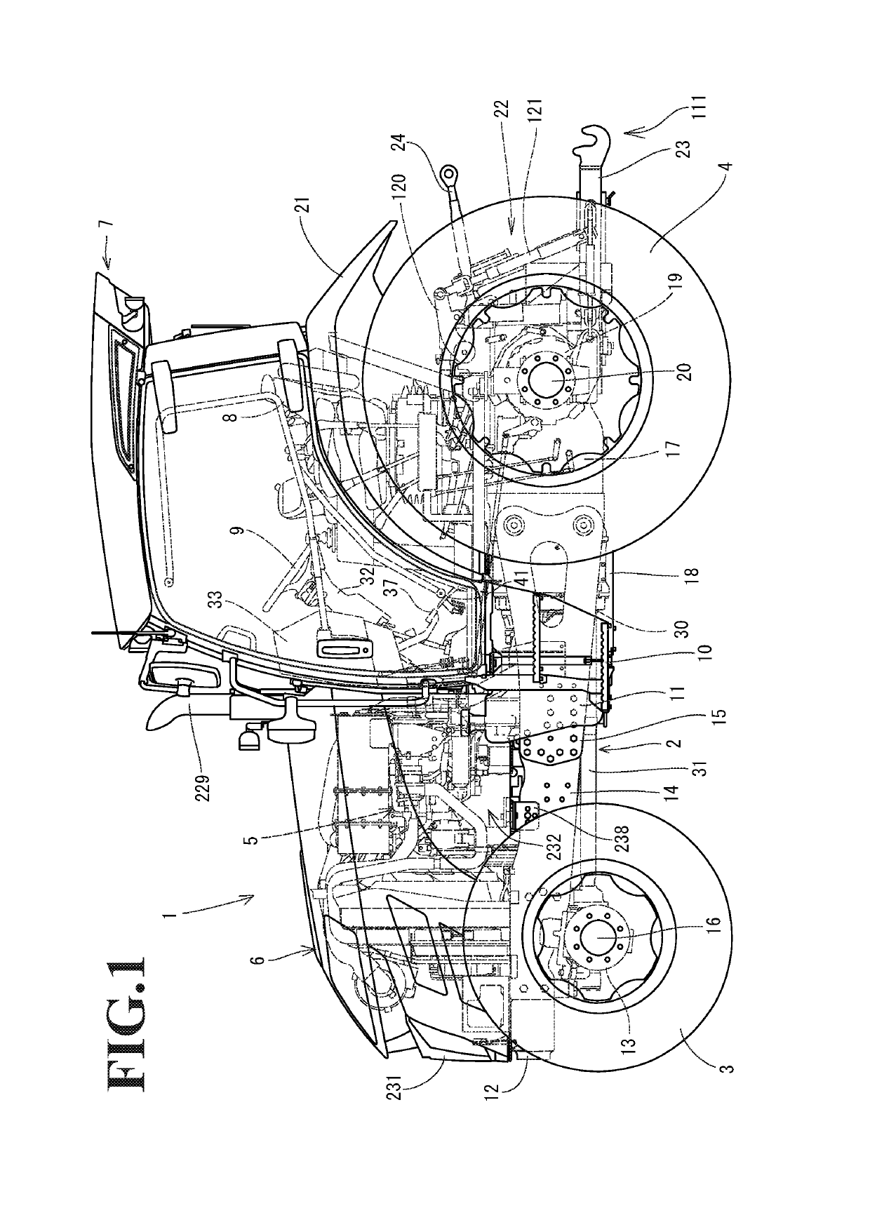
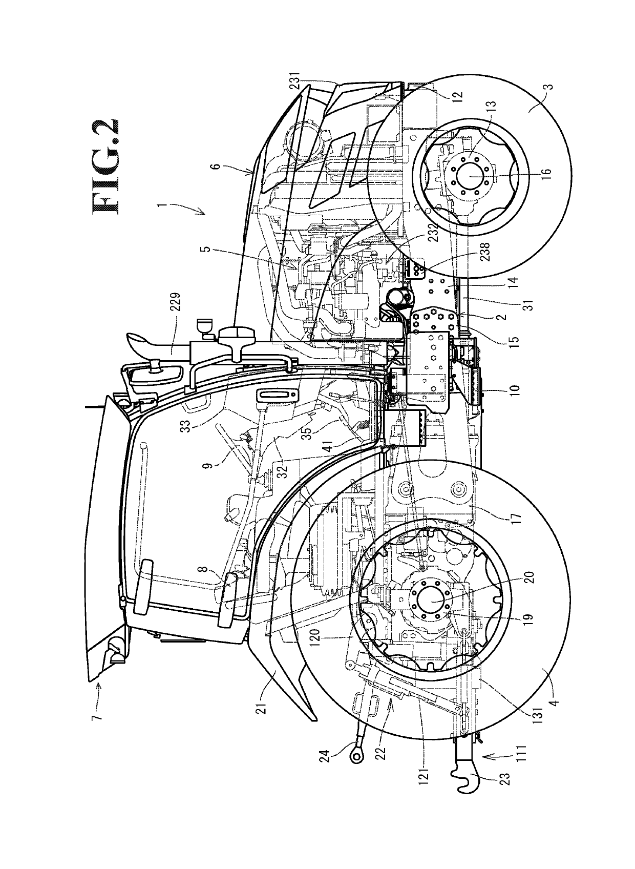
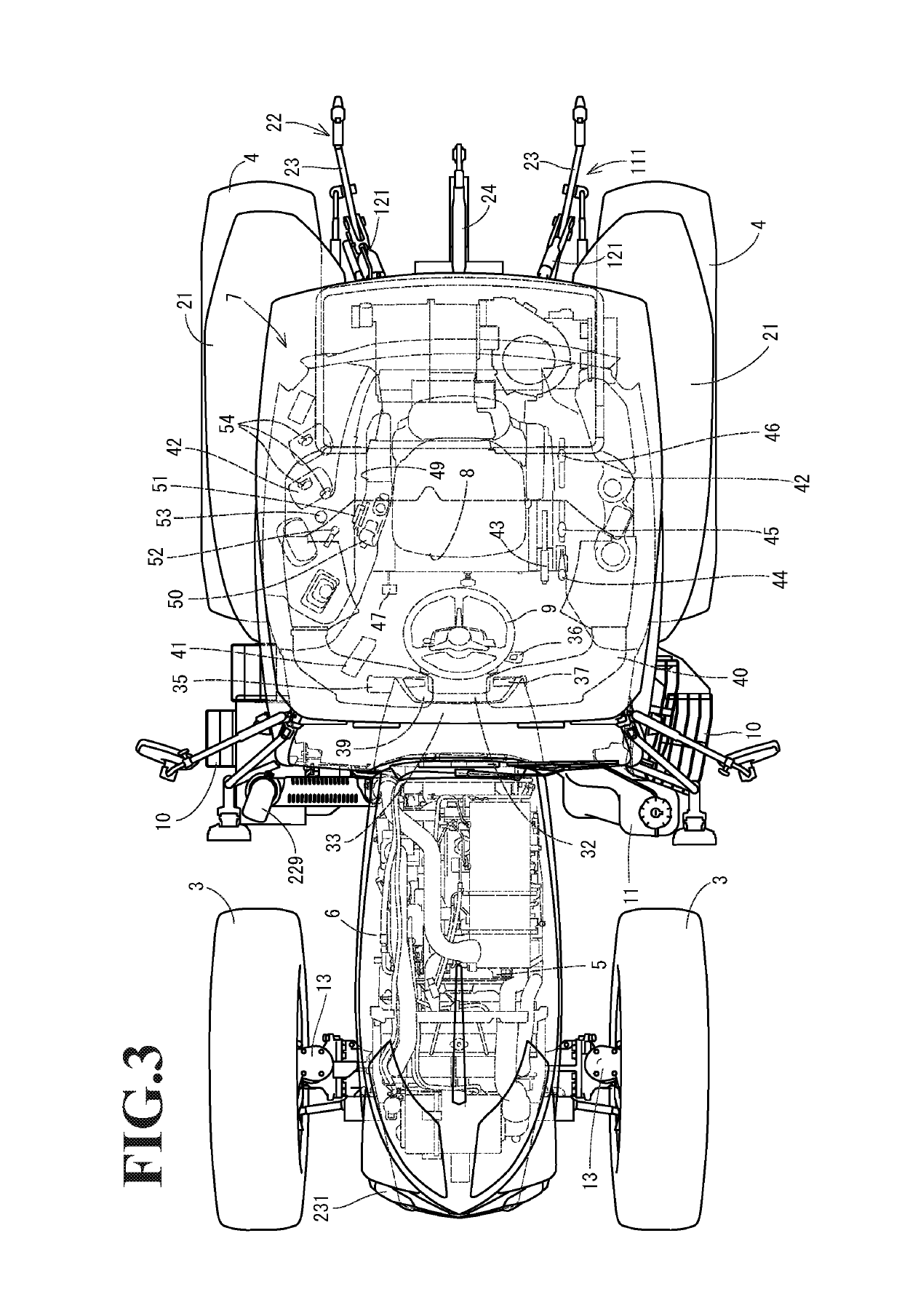
[0063]A farming tractor as an embodiment of the present invention is described below with reference to the drawings. As illustrated in FIG. 1 to FIG. 8, a traveling machine body 2 of a tractor 1 is supported with a pair of left and right front wheels 3 as a traveling unit and with a pair of left and right rear wheels 4 corresponding to a rear traveling unit. A diesel engine 5 (hereinafter, simply referred to as an engine) is mounted on a front portion of the traveling machine body 2 and drives the rear wheels 4 or the front wheels 3, so that the tractor 1 can travel forward and backward. The engine 5 is covered by a hood 6. The traveling machine body 2 has an upper surface provided with a cabin 7. The cabin 7 incorporates an operating seat 8 and a steering wheel 9 for performing a steering operation for the front wheels 3. Steps 10 with which an operator gets on and off the vehicle are provided to left and right outer sides of the cabin 7. Fuel tanks 11 for supplying fuel to the eng...


PUM


Abstract

A work vehicle according to the present invention includes an engine installed in a traveling machine body supported by traveling units, and a transmission case incorporating a hydraulic continuously variable transmission. The transmission case incorporates a forward / backward traveling switching mechanism. The work vehicle includes forward traveling valves for forward traveling hydraulic clutches, a backward traveling valve for a backward traveling hydraulic clutch, and a master valve configured to control hydraulic oil supplying to the forward traveling valves and the backward traveling valve. A part of a hydraulic circuit is formed on a front lid member of the transmission case. The forward traveling valves, the backward traveling valve, and the master valve are attached on a front surface side of the front lid member.

Description

CROSS-REFERENCE TO RELATED APPLICATIONS[0001]The present application is a continuation application of International Application No. PCT / JP2015 / 078377, filed Oct. 6, 2015, which claims priority to Japanese Patent Application No. 2014-211118, filed Oct. 15, 2014 and Japanese Patent Application No. 2015-079704, filed Apr. 9, 2015. The contents of these applications are incorporated herein by reference in their entirety.BACKGROUND OF THE INVENTION[0002]The present invention relates to a work vehicle.[0003]In conventional work vehicles, such as a tractor and a wheel loader, an engine is mounted on a front portion of a vehicle body frame, a transmission case is coupled to a rear portion of the vehicle body frame, and a traveling machine body is supported by front and rear traveling units. For example, the transmission case incorporates a traveling transmission gear mechanism, a differential gear mechanism, a PTO transmission gear mechanism, and the like. Driving force from the engine on t...

Claims


Application Information

Patent Timeline
Patent Type & Authority Patents(United States)
IPC IPC(8): B60K17/08B60K17/344B60K23/08B60T11/12B60T11/28F16H3/093B60K17/22B60K17/10B60K5/02F16H3/14F16H47/04B60T11/21F16H39/42F16H47/02F16H57/025F16H61/00B60K17/06B60T1/06F16C3/03B60K17/28F16H57/02
CPCB60K17/08B60K17/06B60K17/10B60K17/22B60K17/344B60K23/08B60T1/062B60T11/12B60T11/21B60T11/28F16H3/093F16H3/14F16H39/42F16H47/02F16H47/04F16H57/025F16H61/0009B60K5/02F16H2057/02056B60K17/28B60Y2200/221B60Y2410/10F16C3/03B60K17/02B60Y2200/22B60Y2200/416
Inventor HASHIMOTO, YUSUKE
Owner YANMAR POWER TECHNOLOGY CO LTD
Why Eureka
Try Eureka