High-speed plug-in card connector

Active Publication Date: 2019-04-30
AMPHENOL COMML PROD CHENGDU
View PDF32 Cites 0 Cited by
  • Summary
  • Abstract
  • Description
  • Claims
  • Application Information

AI Technical Summary

Benefits of technology

The present invention is a high-speed plug-in card connector with good shielding performance. It uses a metal sheet and conductive plastic to act as a shield, and the plastic shell is wrapped around the terminals for improved signal transmission performance. The design provides a snap joint for reliable contact between the metal sheet and ground terminal, and a positioning groove for easy installation. The method improves assembly accuracy and production efficiency, and the metal snap joint prevents signal interruption and improves signal transmission performance. The invention helps to solve issues like connector skewing and performance affects caused by violent card insertion.

Problems solved by technology

However, both methods have a common defect of poor shielding performance during signal transmission.

Method used


Image

  • High-speed plug-in card connector
  • High-speed plug-in card connector
  • High-speed plug-in card connector

Examples


Embodiment Construction

[0023]Specific embodiments of the present invention will be described below so as to facilitate those skilled in the art to understand the present invention. However, it should be clear that the present invention is not limited to the scope of the specific embodiments. To those of ordinary skill in the art, various changes made within the spirit and scope of the invention as defined and determined by appended claims are deemed as apparent. All inventions that use the inventive concept of the present invention should be deemed as within the protective scope of the present invention.

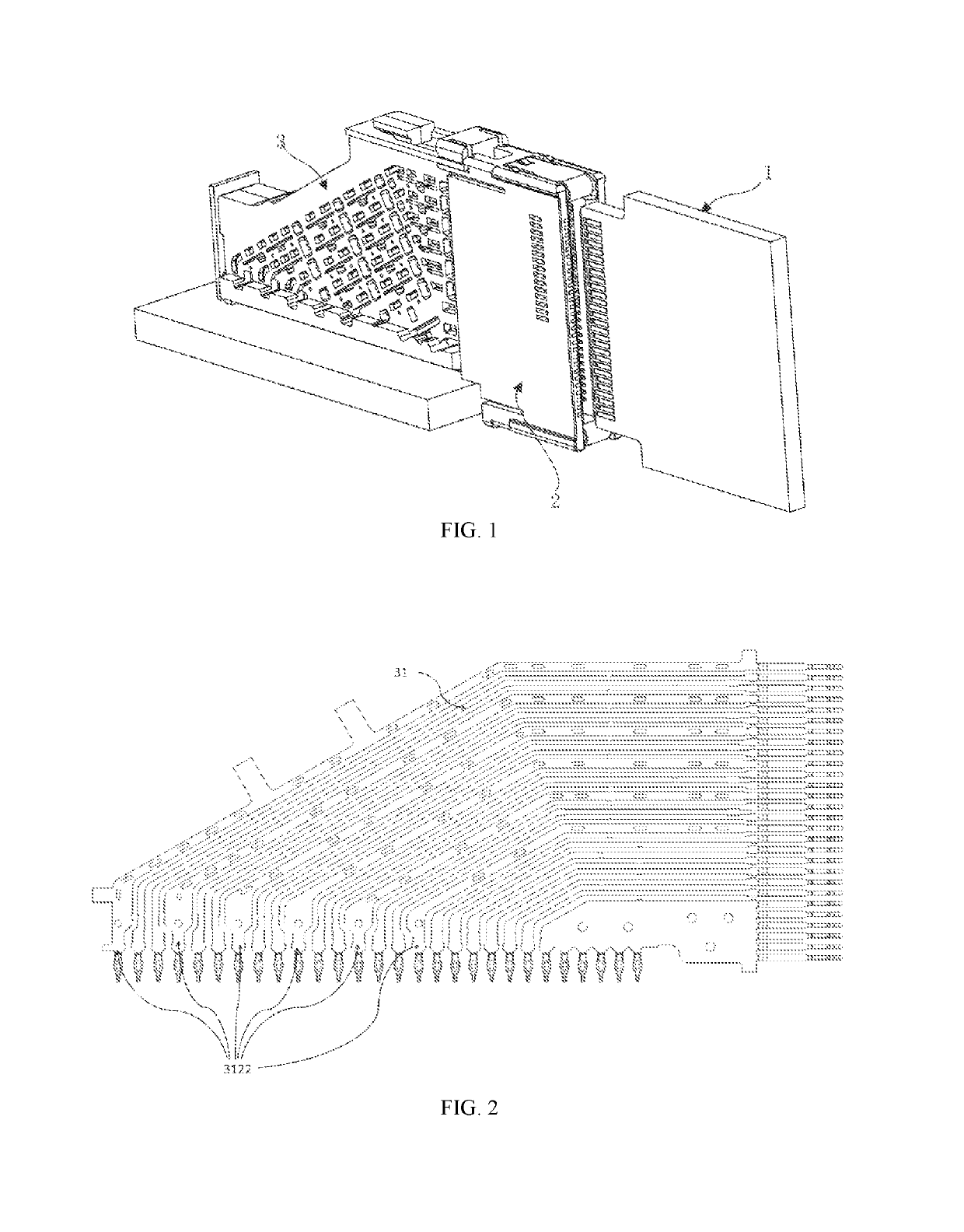
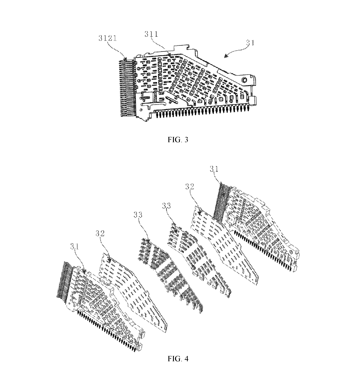
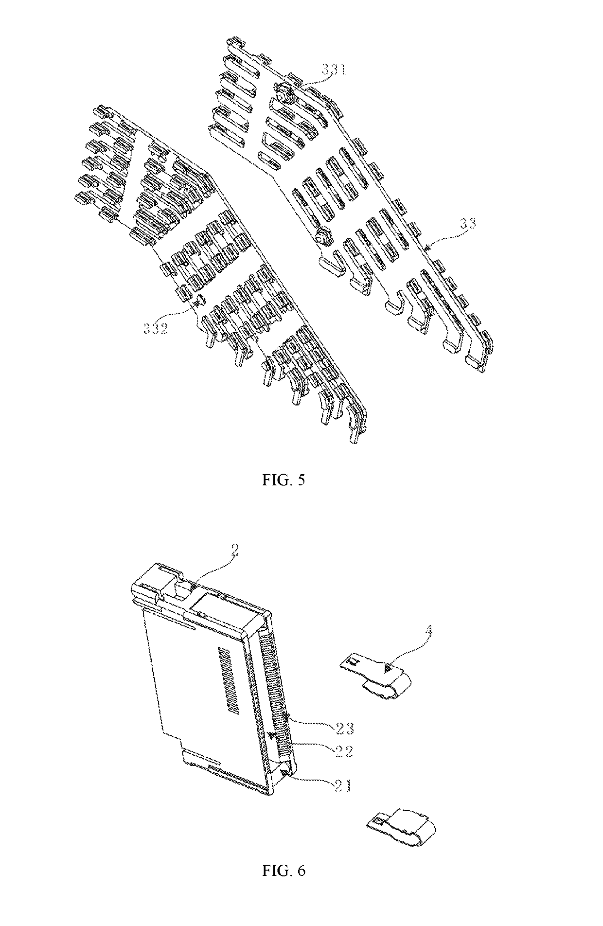
[0024]As shown in FIG. 1, the high-speed plug-in card connector includes housing 2 and two terminal assemblies 3 with reversely arranged internal structure.

[0025]The housing 2 is clamped at the end on the side where the two terminal assemblies 3 are snapped together. A bar-shaped groove 22 is provided recessively at the free end of the housing 2 to receive the electronic card. A contact part 3121 on one si...


PUM


Abstract

A high-speed plug-in card connector comprising two terminal assemblies with reversely arranged internal structure and a housing. Each terminal assembly includes a metal sheet, a conductive plastic, and an injection-molded terminal strip. The conductive plastic is formed on the side of the metal sheet by injection molding and connects the metal sheet with a ground terminal of the terminal strip. The conductive plastics of the two terminal assemblies are located in the very middle of the connector. The conductive plastics fix the two terminal assemblies together with a snap-in connection. The housing is clamped at the end on the side where the two terminal assemblies are snapped together.

Description

CROSS REFERENCE TO RELATED APPLICATIONS[0001]This application is based upon and claims priority to Chinese Patent Application No. CN2017216481458, filed on Dec. 1, 2017, the entire contents of which are incorporated herein by reference.TECHNICAL FIELD[0002]The present invention relates to signal / power transmission devices, and particularly to a high-speed plug-in card connector.BACKGROUND OF THE INVENTION[0003]Presently, for signal transmission, two connectors are respectively connected to two circuit boards and then docked together to achieve signal transmission between the two circuit boards. Besides, in the market, the method in which the signal transmission is achieved by an orthogonal connector respectively connected to two circuit boards is also available. Both methods have their advantages in terms of signal transmission. However, both methods have a common defect of poor shielding performance during signal transmission.SUMMARY OF THE INVENTION[0004]Regarding the above shortc...

Claims


Application Information

Patent Timeline
IPC IPC(8): H01R13/658H01R13/6597H01R12/73H01R13/6596H01R13/11H01R12/72H01R13/26H01R13/6587H01R24/62
CPCH01R13/6587H01R13/26H01R12/721H01R13/113H01R13/6596H01R12/737H01R13/6597H01R24/62
Inventor LIU, XIAOGANGGUO, RONGZHELIAO, LEI
Owner AMPHENOL COMML PROD CHENGDU
Why Eureka
Try Eureka