Electromagnetically operated valve

a technology of electromagnetic operation and valve body, which is applied in the direction of valve operating means/release devices, functional valve types, machines/engines, etc., can solve the problems of magnetic loss in the magnetic circuit of the magnetic drive of the valve, which is too large, and must be overcome, so as to reduce magnetic losses

Active Publication Date: 2019-05-14
FRESENIUS MEDICAL CARE DEUTSCHLAND GMBH +1
View PDF20 Cites 3 Cited by
  • Summary
  • Abstract
  • Description
  • Claims
  • Application Information

AI Technical Summary

Benefits of technology

[0005]It is therefore the object of the present invention to propose an electromagnetically operated valve in particular for use in a device for providing an extracorporeal circulation for treating a patient for dialysis in particular, such that it will overcome the disadvantages mentioned above, in particular losses and wear due to friction, as well as reducing magnetic losses.
[0008]In any case, the magnet armature is supported an aligned in such a way that it can be guided without contact at least in the area of the coil. The support and alignment of the magnet armature as part of the valve slide instead take place on the two axial sides of the magnet armature. It is therefore also possible to omit a guide tube for bearing and guidance of the magnet armature, so that frictional losses and magnetic losses can be reduced and ultimately a long lifetime of the valve is achieved. In addition to exerting a spring force, the spring element fulfills another function of providing frictionless bearing support. These functions can be achieved with a single element, so that the valve according to the invention has a particularly simple and robust design with a small number of components.
[0013]The valve preferably comprises a stop, which cooperates with the guide pin, so that it limits axial movement of the valve slide. The stop may comprise a damping element made of a rubber material, so that the movement of the valve slide is limited to a damping action when the end face of the guide pin strikes the stop. This also results in noise reduction in particular. The stop may be designed as a rubber disk, for example, which is simple and inexpensive to manufacture.

Problems solved by technology

This support causes frictional forces, which cause greater wear and must be overcome by the magnetic force.
In addition, magnetic losses occur in the magnetic circuit of the magnetic drive of the valve due to the nonmagnetic guide tube.

Method used


Image

  • Electromagnetically operated valve
  • Electromagnetically operated valve

Examples


Embodiment Construction

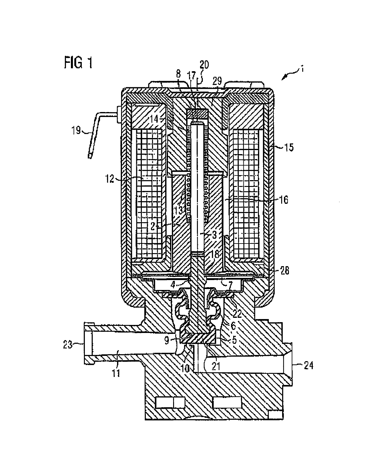
[0020]FIG. 1 shows an electromagnetically operated valve 1, which may be used as a dialysis valve in particular. The valve 1 is provided for controlling a fluid flow in a fluid channel and / or a dialysis machine. To do so, a sealing seat 10 in a fluid channel 11 may be opened and closed between the inlet and outlet ends 23, 24 of the valve 1. The valve 1 has a valve slide that is axially displaceable along an axis of displacement 20 and comprises a magnet armature 2, a guide pin 3 and a ram 4, which are connected to one another by a press fit. The magnet armature 2 forms a part of the so-called magnetic circuit of the valve 1 and is moved in the axial direction by means of the magnetic force generated by a coil 12. In this exemplary embodiment, the magnet armature 2 is moved out of the closed position against the force of a spring 13 and in the direction of a stationary pole part 29. The magnetic force also acts axially against the force of a spring element 7 that is provided for sup...


PUM


Abstract

An electromagnetically operated valve, comprises a valve slide with a magnet armature, which is equipped to close a sealing seat in a fluid channel of the valve with a first axial end in a closed position, as well as a sealing element with folded bellows situated between the sealing seat and the first axial end of the valve slide and separates the valve slide from the fluid channel with a fluid-tight seal. The magnet armature is supported in the valve in an essentially non-contact manner due to the fact that the valve slide has a guide pin protruding in the axial direction from the magnetic armature on a second axial end opposite the first axial end, the guide pin being supported to slide in the axial direction; and the valve slide is aligned in the radial direction on a side of the magnet armature facing the first axial end of the valve slide and is supported so it is movable in the axial direction by means of at least one spring element.

Description

CROSS REFERENCE TO RELATED APPLICATIONS[0001]This application is a National Stage of PCT application PCT / EP2015 / 056082, filed on Mar. 23, 2015, which claims priority to German application 10 2014 005 137, filed Apr. 8, 2014, the entirety of which is hereby incorporated by reference.FIELD OF THE INVENTION[0002]The invention relates to an electromagnetically operated valve, in particular for use in a device for providing an extracorporeal circulation for treating a patient, in particular for dialysis.[0003]Electromagnetically operated valves are used to control the fluid flow in a fluid channel of devices for providing an extracorporeal circulation for treating a patient by dialysis in particular. For valves used in medical applications, it is important that the movable parts of the valve do not come in contact with the fluid. The fluid may be dialysis fluid (dialysate), for example. To this end, such valves usually have a sealing element, which serves to separate the drive of the val...

Claims


Application Information

Patent Timeline
Patent Type & Authority Patents(United States)
IPC IPC(8): F16K31/06A61M39/22F16K15/02F16K41/10A61M1/16F16K1/46
CPCF16K31/0675A61M1/1621A61M39/22F16K41/103F16K15/026F16K31/0655F16K1/46F02M63/0017F16K31/0658
Inventor SCHIEWECK, WERNERDOEHLA, WERNERSEEWALD, OLAFTEICHMANN, MICHAEL
Owner FRESENIUS MEDICAL CARE DEUTSCHLAND GMBH
Why Eureka
Try Eureka