
Brachytherapy position verification system and methods of use

a position verification and brachytherapy technology, applied in the field of position verification systems, can solve the problems of affecting the amount of radiation treatment delivered to the target tissue, the wrong amount of treatment, and the wrong dosage of treatment,

Active Publication Date: 2019-05-21
NUCLETRON OPERATIONS
View PDF20 Cites 6 Cited by
  • Summary
  • Abstract
  • Description
  • Claims
  • Application Information

AI Technical Summary

Benefits of technology

The present patent is about a position verification system for confirming the position of a conduit inserted within a patient. The system includes an elongate control element and a verification element coupled to the control element. The control element is dimensioned for insertion within the conduit and has a proximal end and a distal end. The verification element is coupled to the distal region of the control element and is configured to detect the presence of a reference marker associated with the conduit and transmit a signal indicative of the position of the reference marker relative to the verification element. The system also includes a drive device for controlling movement of the control element through the conduit and a controller for processing the signal transmitted by the verification element. The system can be used in brachytherapy treatment and can help ensure accurate placement of the treatment delivery device.

Problems solved by technology

Movement or misalignment of one or more conduits may affect the amount of radiation treatment delivered to the target tissue.
Misalignment could cause delivery of treatment to the wrong area or delivery of the wrong dosage of treatment to the target area.
Yet, there is often no convenient way to verify positioning of the conduits after the treatment preparation / planning stage to confirm that the treatment will be delivered as planned.
The treatment delivery room may include shielding to accommodate use of radioactive materials and may not be compatible with the imaging and / or tracking devices used during treatment planning.
Yet, inaccuracies may occur when relying on secondary measurements.
For example, any snaking, bunching, or slack that may be created as a wire with a source or sensor is fed into the conduit may result in inaccurate determinations of how far the source or sensor has been inserted and where in the conduit it is located.
Thus, following insertion of the conduit into the body for treatment planning purposes, the conduit may shift within the body, and current systems may not be able to directly determine spatial positioning of the conduit.
Consequently, current systems may be unable to directly or accurately verify the ultimate location of the radiotherapy source when delivered to the conduit.
Shifting of the conduit after the imaging during treatment planning or preparation may go undetected, resulting in inaccurate radiation treatment for the patient.
Additionally, it may be difficult or impossible to synchronize positioning data across the various systems, resulting in potential undetected discrepancies or inefficiencies.
Because each system measures positional information differently, it may be difficult, if not impossible, to merge or synchronize this data.
Further, current methods of position verification, including medical imaging (e.g., radiography, X-ray, MRI, ultrasound), electromagnetic tracking, optical shape sensing, or in vivo dosimetry may be expensive, complex, unwieldy, may disturb the workflow, or may cause harm or discomfort to the patient.
Additionally, these devices may not be integrated into the treatment delivery system and consequently their feedback cannot be easily or safely used to interrupt or adjust treatment delivery if an inconsistency is detected as treatment occurs.
Unintentionally switching one or more transfer tubes when connecting the conduits to the afterloader for treatment delivery may thus result in wrong or inaccurate delivery of radiation to the patient.

Method used


Image

  • Brachytherapy position verification system and methods of use
  • Brachytherapy position verification system and methods of use
  • Brachytherapy position verification system and methods of use

Examples


Embodiment Construction

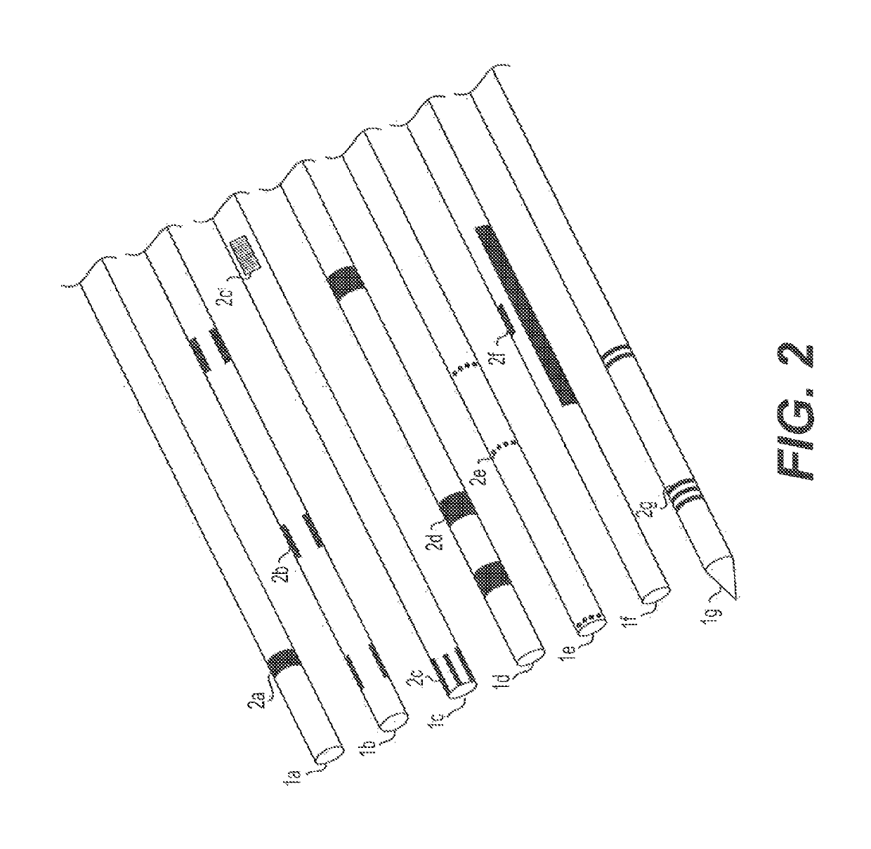
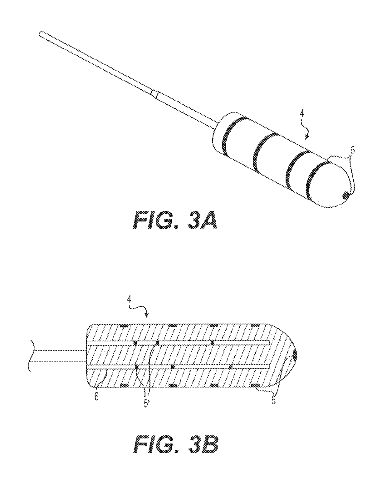
[0043]Reference will now be made in detail to the exemplary embodiments of the present disclosure described below and illustrated in the accompanying drawings. Wherever possible, the same reference numbers will be used throughout the drawings to refer to same or like parts. For purposes of this disclosure, “proximal” refers to an end closer to the source of treatment (e.g., afterloader), and “distal” refers to an end further from the source of treatment. “Radiotherapy source” refers to a radioactive or x-ray source and encompasses both sources used for therapeutic and non-therapeutic purposes. “Communication” may refer to receiving signals, transmitting signals, or both receiving and transmitting signals. Additionally, the term “conduit” may refer to a catheter, needle, tube, applicator, applicator channel, or any suitable delivery pathway for a radiotherapy source.

[0044]While the present disclosure is described herein with reference to illustrative embodiments for particular applic...


PUM


Abstract

In one embodiment, a verification system for confirming the position of a conduit inserted within a patient may include an elongate control element dimensioned for insertion within the conduit. The control element has a proximal end and a distal end, and a verification element coupled to a distal region. The verification element may be configured to detect the presence of a reference marker associated with the conduit and communicate a signal indicative of the position of the reference marker relative to the verification element. The control element may also be configured to maneuver the verification element along a length of the conduit. The system may also include a drive device coupled to a proximal region of the control element for controlling movement of the control element through the conduit, a controller associated with the verification element and configured to communicate with the verification element, and a signal conductor for conducting the signal between the verification element and the controller.

Description

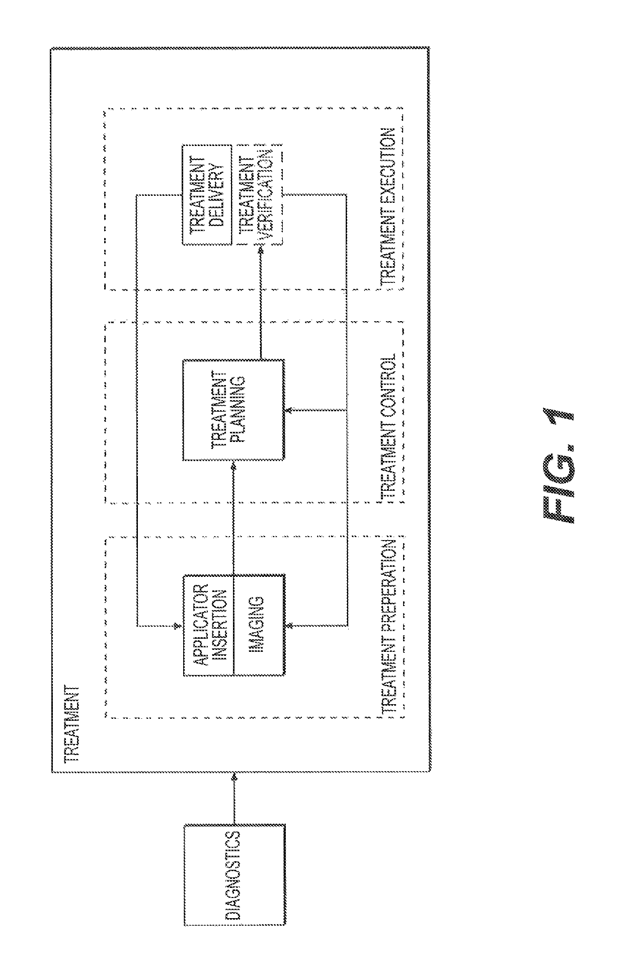
TECHNICAL FIELD[0001]Embodiments of the present disclosure relate to position verification systems, and more particularly, to brachytherapy systems for verifying the positioning of a conduit configured to receive a radiotherapy source once the conduit is within a patient.BACKGROUND INFORMATION[0002]Brachytherapy is a method of treating cancer by placing one or more radiotherapy sources in or by an area of tissue requiring treatment. Delivering radiation directly and accurately to the target treatment area may allow a clinician to administer higher doses of radiation while decreasing the impact on surrounding, healthy tissue.[0003]In a typical brachytherapy treatment method, prior to treatment delivery, one or more conduits, for example, a brachytherapy applicator, a needle, a tube, or a catheter, is positioned within a target treatment area. The conduit is connected to a source of treatment, and a radiotherapy source is delivered from the treatment source and through the conduit int...

Claims


Application Information

Patent Timeline
Patent Type & Authority Patents(United States)
IPC IPC(8): A61B17/00A61B34/20A61N5/10A61B90/00
CPCA61B90/39A61B90/30A61N5/1001A61B17/00234A61B34/20A61N5/1039A61N5/1048A61N5/1075A61B2090/309A61B2034/2051A61B2090/378A61B2090/376A61B2090/374A61B2017/00323A61B2090/3983A61N5/1002A61N5/103A61N5/1007A61N5/1014A61N5/1015A61N5/1016A61N5/1017A61N5/1027A61N5/1028A61N5/1029A61N2005/1008A61N2005/1051A61B2090/3937A61B2034/2055
Inventor DE VRIES, FRITSVAN APPELDOORN, ADRIAAN
Owner NUCLETRON OPERATIONS
Learn More