Soldering apparatus and flux-applying device

a technology of flux application and soldering apparatus, which is applied in the direction of soldering apparatus, manufacturing tools, and auxillary welding devices, etc., can solve the problems of difficult movement of the nut, difficult adjustment of the fixed position of the nut to the screw shaft, and difficulty in removal. , to achieve the effect of reducing time and costs, smooth rotation, and easy adjustment of the fixed position of the nu

Active Publication Date: 2019-05-21
SENJU METAL IND CO LTD
View PDF33 Cites 0 Cited by
  • Summary
  • Abstract
  • Description
  • Claims
  • Application Information

AI Technical Summary

Benefits of technology

[0024]By the nut used for this invention, it is possible to strip the adhered matter by a function of the non-meshing part even when the adhered matter is fixed to the screw shaft which the nut meshes. Since the non-meshing part strips off or scraps the adhered matter without fixing the adhered matter stripped by the nut to another screw shaft (valley of screw) again, it stops the prevention of the revolution of the screw shaft by the stripped adhered matter (scrapped matter), so that the screw shaft smoothly rotates. As a result thereof, it is possible to change (adjust) a fixed position of the nut easier that the conventional case.
[0025]By the soldering apparatus and the flux-applying device according to the invention, since any flux fumes which are adhered and solidified to the members (screw shaft and nut) for changing the fixed position thereof to match the width of the substrate in the apparatus and device are removed while they are scrapped, a forward or backward movement of the nut to the screw shaft becomes easy so that it is easily possible to change the fixed position of the nut. Accordingly, it is easily possible to remove the flux adhered to the screw shaft and to adjust the fixed position of the rails for conveying the substrate, the substrate-supporting portion or the like to match a size of the substrate. Since it is easily possible to remove the adhered flux, it is possible to reduce time and costs required for maintenance of the apparatus or device. Further, since the soldering apparatus and the flux-applying device according to the invention have such a configuration that the fixed position of the nut is changeable by revolving the screw shaft, upper and lower positions of the non-meshing part do not alter even when changing the foxed position of the nut. Accordingly, the removed adhered matter can be caught by the revolution of the screw shaft again and exhausted to outside of the nut without preventing the forward or backward movement of the nut.

Problems solved by technology

Since the solidified flux fumes are hard to be removed and are strongly adhered, it is not easily possible to remove them by revolving the screw shaft.
Accordingly, a movement of the nut is difficult so that it is very difficult to adjust the fixed position thereof to the screw shaft.
In this case, like the above-mentioned case, it is not also easily possible to remove them by revolving the screw shaft.
Accordingly, a movement of the nut is difficult so that it is very difficult to adjust the fixed position thereof to the screw shaft.
In the flux-applying device, dripped flux is also adhered to the screw shaft and solidified so that the fixed flux is hard to be easily stripped by the revolution of the screw shaft.
Accordingly, any similar problems occur such that the fixed position of the nut to the screw shaft cannot be changed by its movements.

Method used


Image

  • Soldering apparatus and flux-applying device
  • Soldering apparatus and flux-applying device
  • Soldering apparatus and flux-applying device

Examples


first embodiment

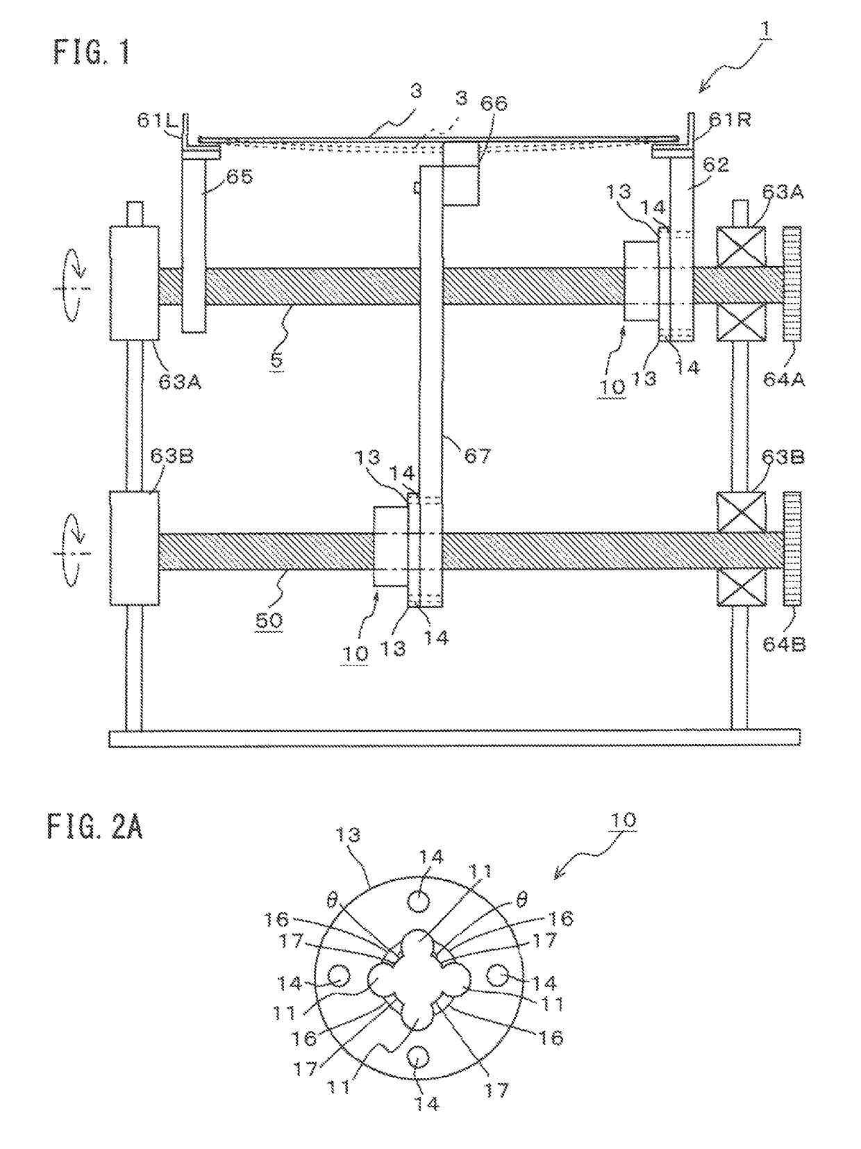
[0034]A configuration example of a soldering apparatus 1 as the first embodiment according to the invention will be described with reference to FIGS. 1 through 3.

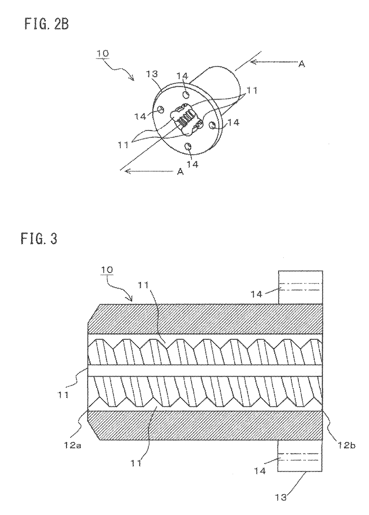
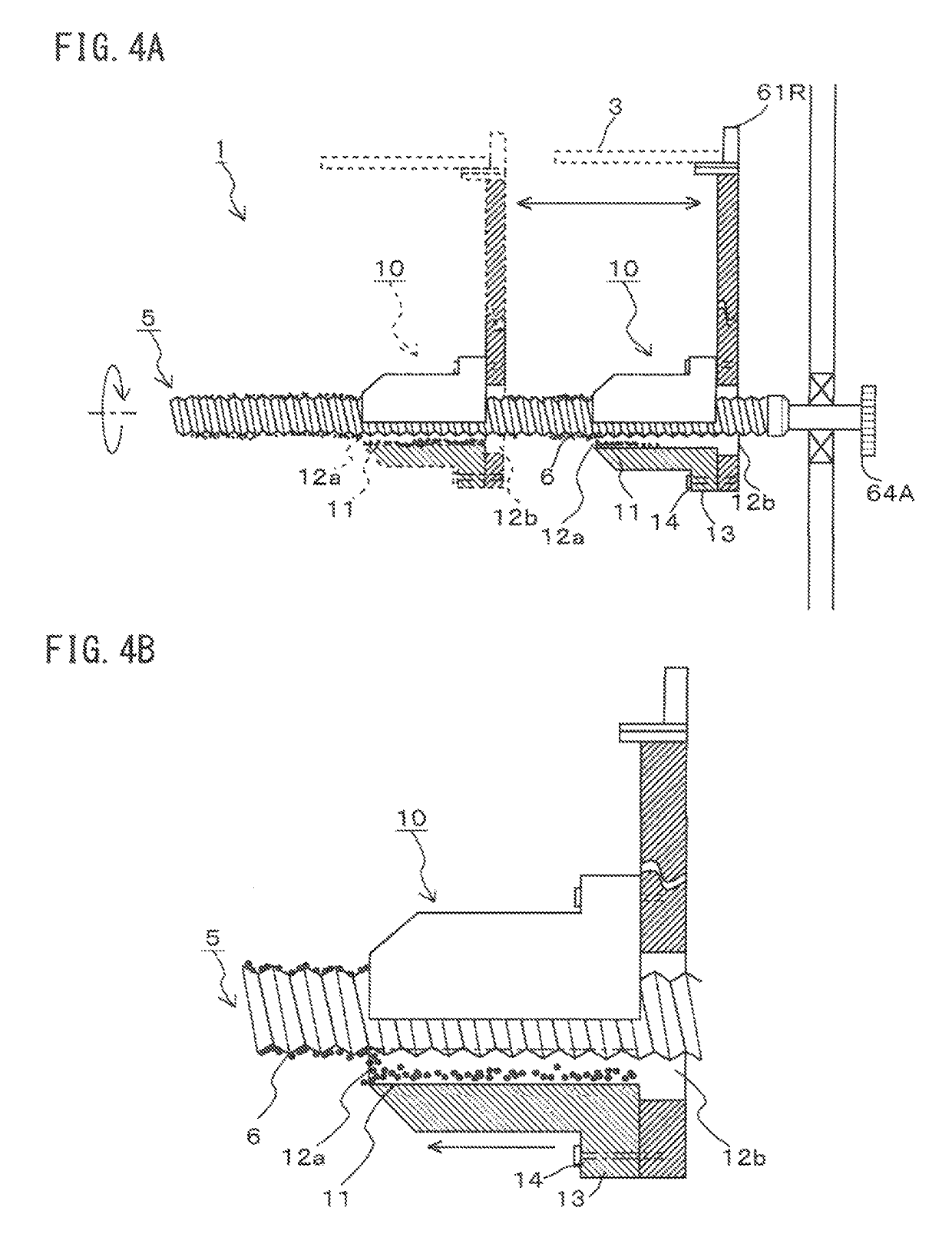
[0035]As shown in FIG. 1, the soldering apparatus 1 is a device for soldering by heating and processing, for example, the printed circuit board 3 or the like in which solder paste is applied to predetermined electrodes. The soldering apparatus 1 is provided with a pair of conveying rails 61L, 61R, a substrate-supporting portion 66 for supporting the printed circuit board 3 from below along a vertical direction to match a width of the printed circuit board 3, and an adjusting member being changed to match the width of the printed circuit board 3. As this adjusting member, screw shafts 5, 50 and nuts 10 that are respectively configured to be able to change their fixed positions with regards to the screw shafts 5, 50 are provided.

[0036]The conveying rail 61L is set to be a fixed rail and the conveying rail 61R is set to be a m...

second embodiment

[0059]The following will describe a configuration example of the flux applying device 2 as a second embodiment with reference to FIG. 5. Like codes are applied to like members of the first embodiment, the detailed explanation of which will be omitted.

[0060]The flux applying device 2 according to the invention is provided with a pair of conveying rails 61L, 61R, and an adjusting member which is changed to match the width of the printed circuit board 30. As this adjusting member, a screw shaft 5 having a predetermined length and a nut 10 that screws on to the screw shaft 5 and is configured to be able to change its fixed position to match the screw shaft 5 are provided.

[0061]The conveying rail 61L is set to be a fixed rail and the conveying rail 61R is set to be a movable rail. As the adjusting member for changing a fixed position of the conveying rail 61R, the flux-applying device 2 is provided with the following members. The conveying rail 61R is supported by a rail-supporting porti...


PUM

PropertyMeasurementUnit
angleaaaaaaaaaa
widthaaaaaaaaaa
flexibilityaaaaaaaaaa

Abstract

A soldering apparatus including a flux-applying device having a nut that is fitted into the soldering apparatus and the flux-applying device can change a fixed position of the nut easier than that of a convention example even if any adhered matters generated when each apparatus or device is used for a long time are adhered. The nut screws on to the screw shaft having a predetermined length. The nut is provided with at least one non-meshing part that does not mesh with the screw shaft and is formed parallel to a movement direction thereof. The non-meshing part extends from a forward end of the nut to a rear end thereof along whole length of the nut.

Description

CROSS-REFERENCE TO RELATED APPLICATIONS[0001]This application is the United States national phase of International Application No. PCT / JP2016 / 054595 filed Feb. 17, 2016, and claims priority to Japanese Patent Application No. 2015-105390 filed May 25, 2015, the disclosures of which are hereby incorporated in their entirety by reference.TECHNICAL FIELD[0002]The present invention relates to a soldering apparatus and a flux-applying device, which use a nut that is applicable to the soldering apparatus, the flux-applying device for applying the flux or the like, in connection with mounting of electronic components on a printed circuit board. It specifically relates to the soldering apparatus and the flux-applying device, which use a nut that does not hinder the screw shaft from revolving even when a part of the flux evaporated by the soldering or the flux-applying or the flux is adhered and fixed to the screw shaft or the like.BACKGROUND TECHNOLOGY[0003]A soldering apparatus for solderin...

Claims


Application Information

Patent Timeline
Patent Type & Authority Patents(United States)
IPC IPC(8): B23K1/08B23K37/04B23K1/00B23K1/20H05K3/34B23K1/008B23K3/00
CPCB23K37/0408B23K1/00H05K3/34B23K3/00B23K1/008B23K1/0008B23K1/203B23K3/082B23K3/08B23K2101/42B23K1/0016B23K3/087
Inventor SUGIHARA, TAKASHITAGUCHI, HIROSHIHIYAMA, TSUTOMU
Owner SENJU METAL IND CO LTD
Why Eureka
Try Eureka