
Exhaust gas purification system for internal combustion engine

a technology for exhaust gas purification and internal combustion engines, which is applied in the direction of exhaust treatment electric control, electrical control, machines/engines, etc., can solve the problems of inability to meet the requirements of the market, especially volatility, of diesel engine fuel available in the market, and achieve the reduction of nox stored and limited storage capacity of nsr catalysts.

Inactive Publication Date: 2019-05-21
TOYOTA JIDOSHA KK
View PDF2 Cites 0 Cited by
  • Summary
  • Abstract
  • Description
  • Claims
  • Application Information

AI Technical Summary

Benefits of technology

The patent text describes an exhaust gas purification system for an internal combustion engine that uses an NSR catalyst to reduce NOx. The system is designed to determine the optimal temperature for fuel supply based on the fuel's cetane number, which correlates with its volatility. By adjusting the fuel supply based on this information, the system can ensure sufficient reduction of NOx by fuel in the NSR catalyst while minimizing fuel adhesion to the catalyst. Additionally, the system can stop the fuel supply and adjust the threshold for fuel supply based on the temperature of the exhaust gas, ensuring optimal reaction between fuel and NOx in the catalyst. Overall, this system allows for effective reduction of NOx and efficient fuel supply in exhaust gas purification systems for internal combustion engines.

Problems solved by technology

However, properties (in particular the volatility) of diesel engine fuels available in the market are not always uniform but vary to some extent.

Method used


Image

  • Exhaust gas purification system for internal combustion engine
  • Exhaust gas purification system for internal combustion engine
  • Exhaust gas purification system for internal combustion engine

Examples


first embodiment

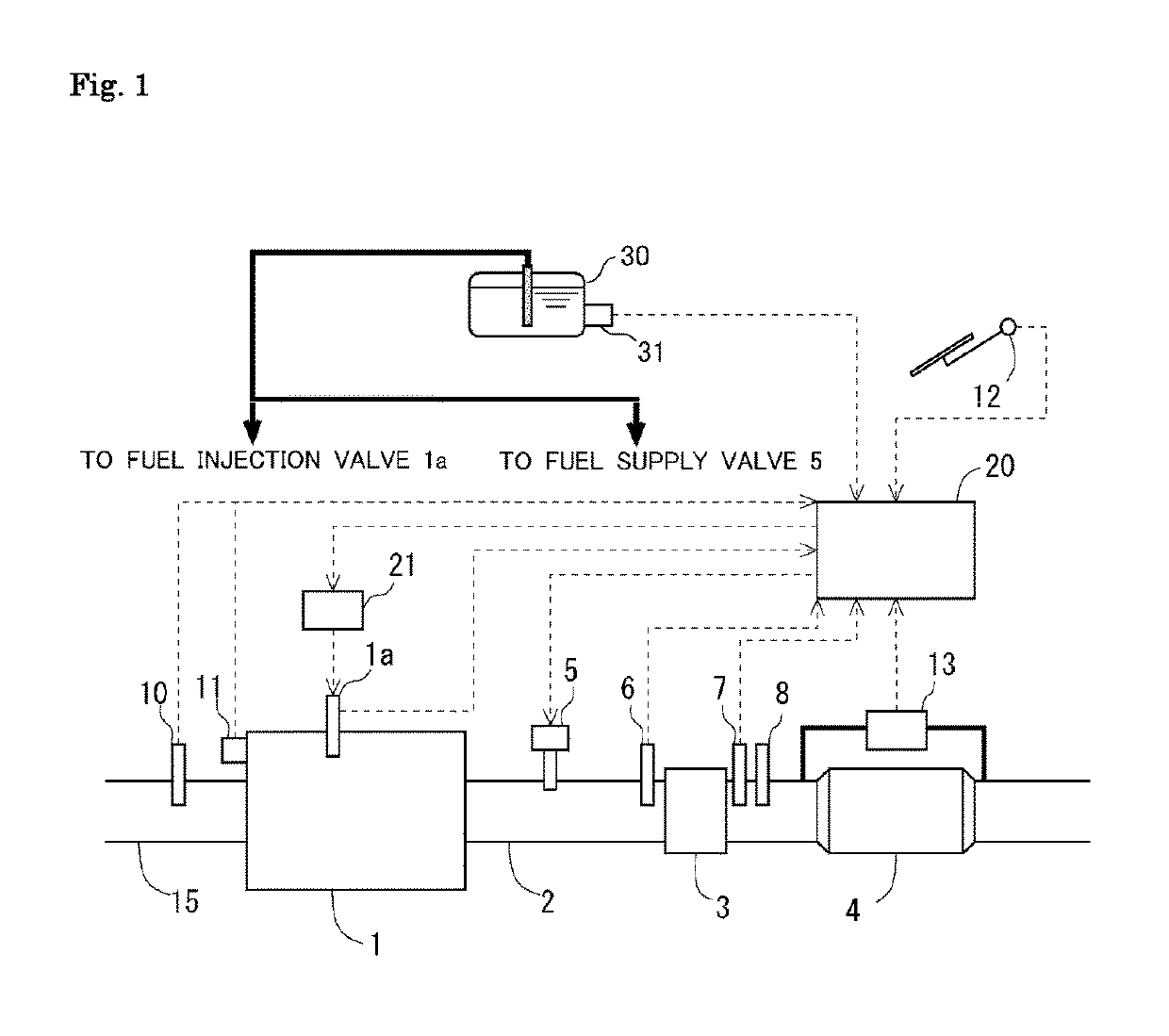
[0034]FIG. 1 shows the general configuration of an exhaust gas purification system for an internal combustion engine 1 according to the present disclosure. The internal combustion engine 1 shown in FIG. 1 is a diesel engine for driving a vehicle. The internal combustion engine operates by burning an air-fuel mixture having a lean air-fuel ratio higher than the theoretical air-fuel ratio. The internal combustion engine 1 is connected with an exhaust passage 2. The exhaust passage 2 is provided with an NSR catalyst 3, which stores NOX contained in the exhaust gas when the exhaust gas has a lean air-fuel ratio and desorbs NOX stored therein to let the desorbed NOX be reduced by unburned fuel in the exhaust gas when the exhaust gas has a rich air fuel-ratio. The exhaust passage 2 is also provided with a particulate filter 4 (which will be simply referred to as the “filter” hereinafter) that traps PM in the exhaust gas, which is arranged downstream of the NSR catalyst 3.

[0035]The exhaust...

second embodiment

[0064]Next, NOX reduction control according to a second embodiment of the present disclosure will be described with reference to flow charts shown in FIGS. 6 and 7. The processing steps in the NOX reduction control shown in FIGS. 6 and 7 that are the same as those in the NOX reduction control shown in FIG. 4 are denoted by the same reference signs and will not be described further.

[0065]In the NOX reduction control shown in FIGS. 6 and 7, the processing of the steps S207 and S208 in the NOX reduction control shown in FIG. 4 is replaced by the processing of steps S401 to S409 in FIG. 7. Specifically, if an affirmative determination is made in step S206, the process proceeds to step S401.

[0066]In step S401, it is determined whether or not the air-fuel ratio of the exhaust gas flowing out of the NSR catalyst 3 measured by the air-fuel ratio sensor 8 is higher than a specific air-fuel ratio Af0, namely whether or not this exhaust gas air-fuel ratio is leaner than the specific air-fuel r...

embodiments

Modification of Embodiments

[0072]In the NOX reduction control according to FIGS. 6 and 7, the processing of steps S401 and S402 relating to the compensation of the quantity of fuel supplied through the fuel supply valve 5 is performed after starting the NOX reduction process and after making the determination as to whether or not reduction of NOX in the NSR catalyst 3 is carried out appropriately (in the processing of step S206). Alternatively, the processing of steps S401 and S402 relating to the compensation of the quantity of fuel supplied through the fuel supply valve 5 may be performed after starting the NOX reduction process but before making the determination as to whether reduction of NOX in the NSR catalyst 3 is carried out appropriately. In this case, the determination as to whether reduction of NOX in the NSR catalyst 3 is carried out appropriately (i.e. the processing of step S206 or S404) is made after confirming the absence of a trouble of the fuel supply valve 5 and p...


PUM


Abstract

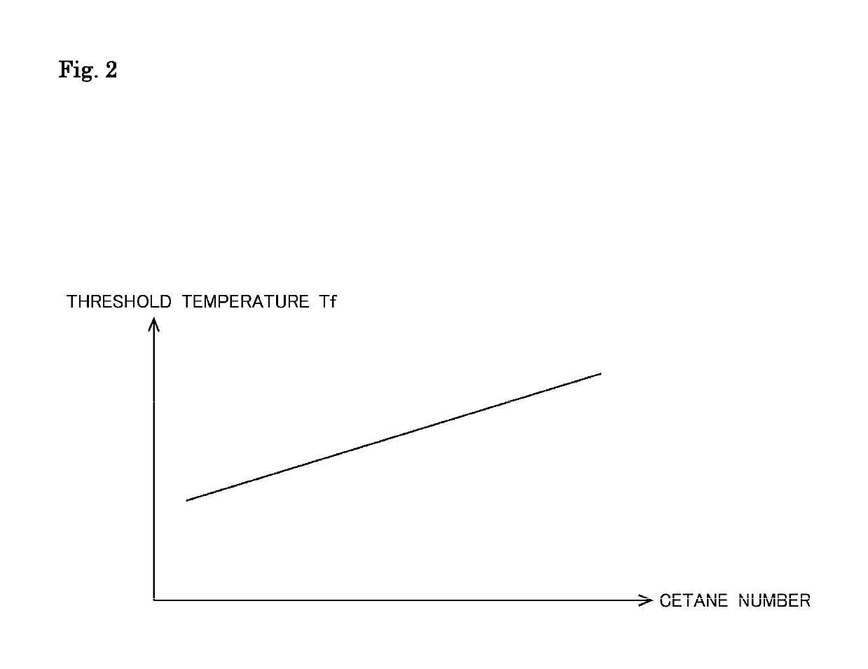
When the temperature of the exhaust gas flowing into an NSR catalyst exceeds a specific threshold temperature that is determined on the basis of the cetane number of fuel in such a way that the specific threshold temperature is set lower when the cetane number of the fuel is low than when it is high, fuel is supplied to the exhaust gas by fuel supply device to perform an NOX reduction process for the NSR catalyst. If the quantity of heat generated in the NSR catalyst per unit time is smaller than a specific value while the NOX reduction process is being performed, the NOX reduction process in progress is suspended, and the NOX reduction process is performed later on when the temperature of the exhaust gas flowing into the NSR catalyst exceeds an updated threshold temperature higher than the specific threshold temperature.

Description

CROSS-REFERENCE TO RELATED APPLICATIONS[0001]This application claims priority to Japanese Patent Application No. 2016-198935, filed on Oct. 7, 2016, which is hereby incorporated by reference herein in its entirety.BACKGROUNDTechnical Field[0002]The present disclosure relates to an exhaust gas purification system for an internal combustion engine.Background Art[0003]Internal combustion engines are provided with a filter arranged in the exhaust passage to prevent or reduce emissions of particulate matter (which will be hereinafter referred to as “PM”) in the exhaust gas to the external environment. PM in the exhaust gas is gradually deposited in this filter as the operation of the internal combustion engine continues. To avoid clogging of the filter, a filter regeneration process is performed (see, for example, Patent Literature 1). In the case of diesel engines, in which the exhaust gas has, in general, a lean air-fuel ratio higher than the theoretical air fuel ratio continuously, a ...

Claims


Application Information

Patent Timeline
Patent Type & Authority Patents(United States)
IPC IPC(8): F01N3/20F01N3/08F02D41/02F02D41/40F02D41/00F01N9/00
CPCF01N3/206F01N3/0842F02D41/0025F02D41/0245F02D41/0275F02D41/40F01N3/0814Y02T10/44F01N3/2033F01N9/00F01N2610/03F01N2900/1404F01N2900/1602F01N2900/1631F02D2041/0265F02D2200/0602F02D2200/0611Y02T10/24Y02T10/26Y02T10/12Y02T10/40
Inventor SUZUKI, HAYATO
Owner TOYOTA JIDOSHA KK
Learn More