
Electrochemical cell

a technology of electrochemical cells and thin film batteries, applied in the direction of batteries, sustainable manufacturing/processing, instruments, etc., can solve the problems of reducing the storage capacity of the battery, affecting the performance of the battery, etc., to achieve the effect of increasing the size of the cathode and the anode, saving space and increasing the storage capacity

Active Publication Date: 2019-08-27
THE SWATCH GRP RES & DEVELONMENT LTD
View PDF18 Cites 0 Cited by
  • Summary
  • Abstract
  • Description
  • Claims
  • Application Information

AI Technical Summary

Benefits of technology

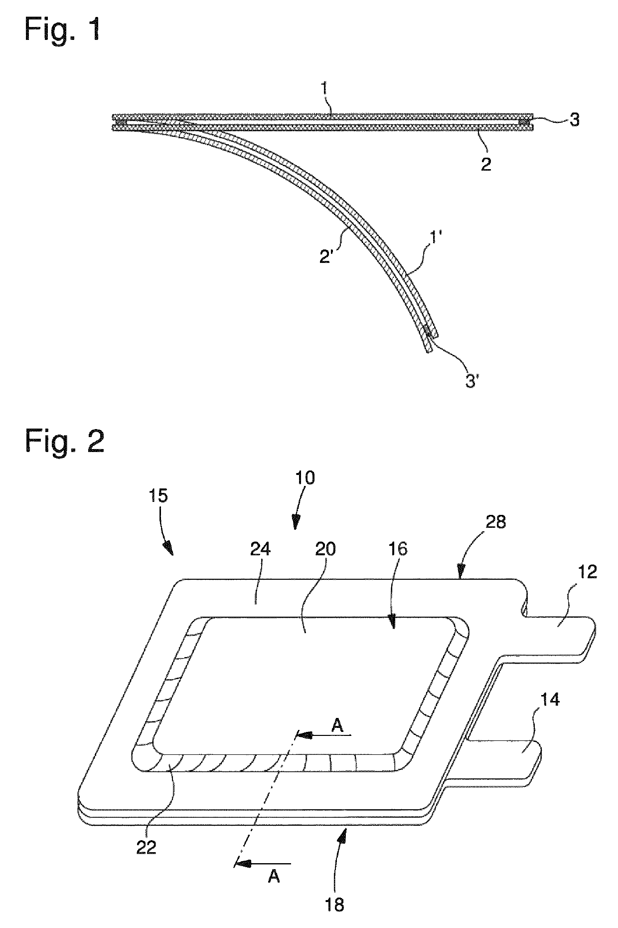
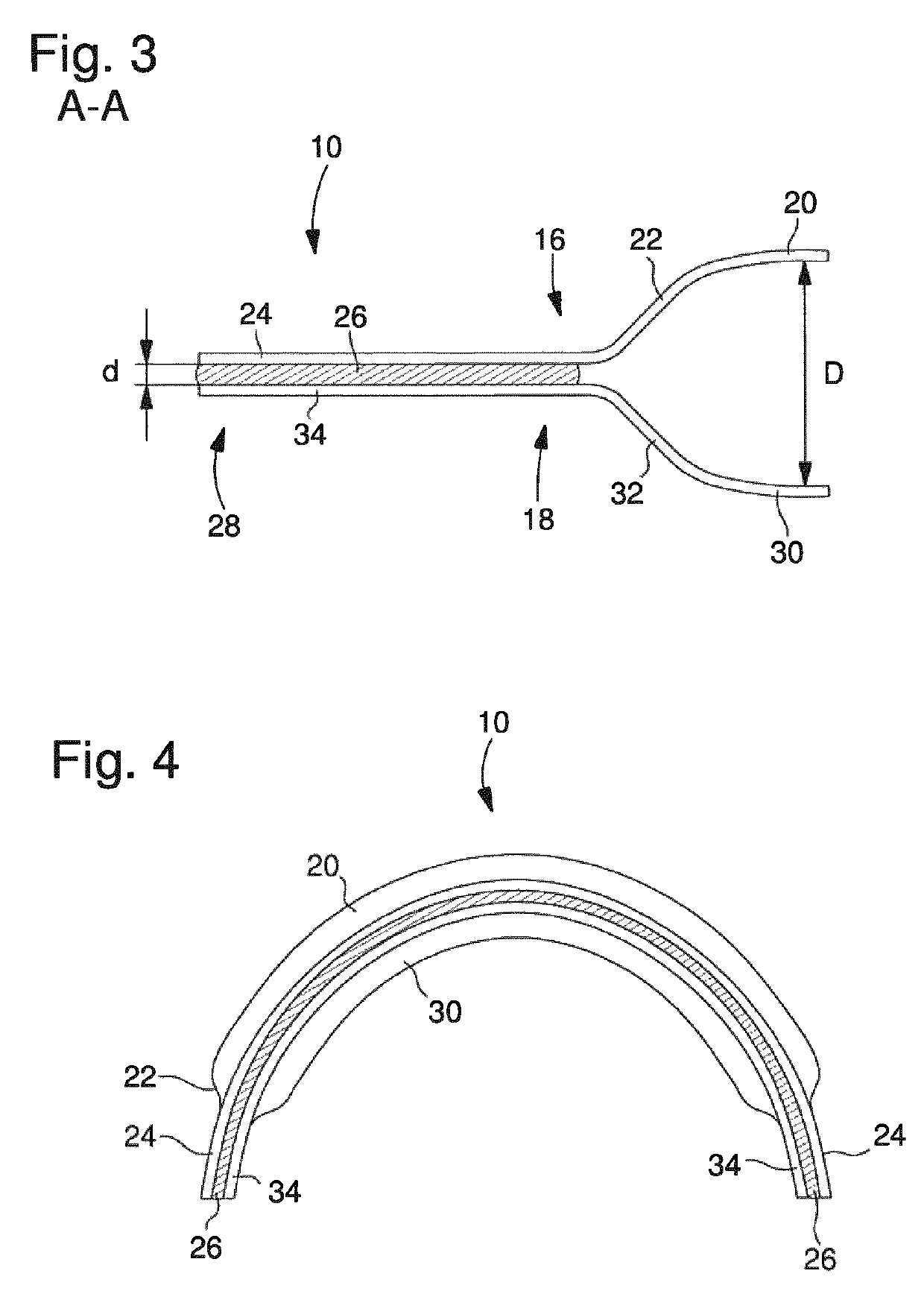
[0015]Hence, at least one of first and second current collectors comprises an embossed or deformed surface portion to reduce the distance to the other current collector. In this way, the distance D between the collecting sections of first and second current collectors can be kept in a range that is reasonable for the electrochemical function of first and second current collectors while the distance d between first and second connecting sections can be reduced to enable use of adhesive material between first and second connecting sections that provides a sufficient tightness even under bending or folding conditions.
[0043]Apart from this mechanical aspect the current collectors may be integrally formed with anode and cathode collector tabs. A separate interconnection of connector tabs and current collectors may therefore become superfluous. In this way, a rather space saving arrangement can be provided for an electrochemical cell. Since a separate encapsulation or housing is no longer required, the size of cathode and anode can be increased without increasing the outer dimensions of the electrochemical cell itself. Consequently, the storage capacity and hence the energy density of the electrochemical cell can be increased.

Problems solved by technology

Since the current collectors are typically arranged at the outside facing portions of anode and cathode, they may become particularly subject to mechanical stress when the electrochemical cell is bent.
In practical applications and in particular after a number of bending or folding operations, e.g. after about 100 or 500 bending operations on a radius of curvature of 10 mm, conventional current collectors may exhibit a fissured structure or may even tend to show damaged portions at least on their surface.
Such current collectors typically formed on the basis of metal foils therefore tend to deteriorate and leak in response to repeated bending or folding operations.
On the one hand, rather flexible or elastic deformable adhesives may not provide sufficient gas barrier properties so that a multilayer structure or a respective electrochemical cell may exhibit overly fast aging.
However, when mutually bonding two current collectors in a battery application, serving as anode current collector and as cathode current collectors, their distance with respect to each other cannot be reduced below a predefined minimum of e.g. 400 μm.
Otherwise, a desired electrical capacity of the battery cannot be achieved due to a reduced volume for the electro-active material.

Method used


Image

  • Electrochemical cell
  • Electrochemical cell
  • Electrochemical cell

Examples


Embodiment Construction

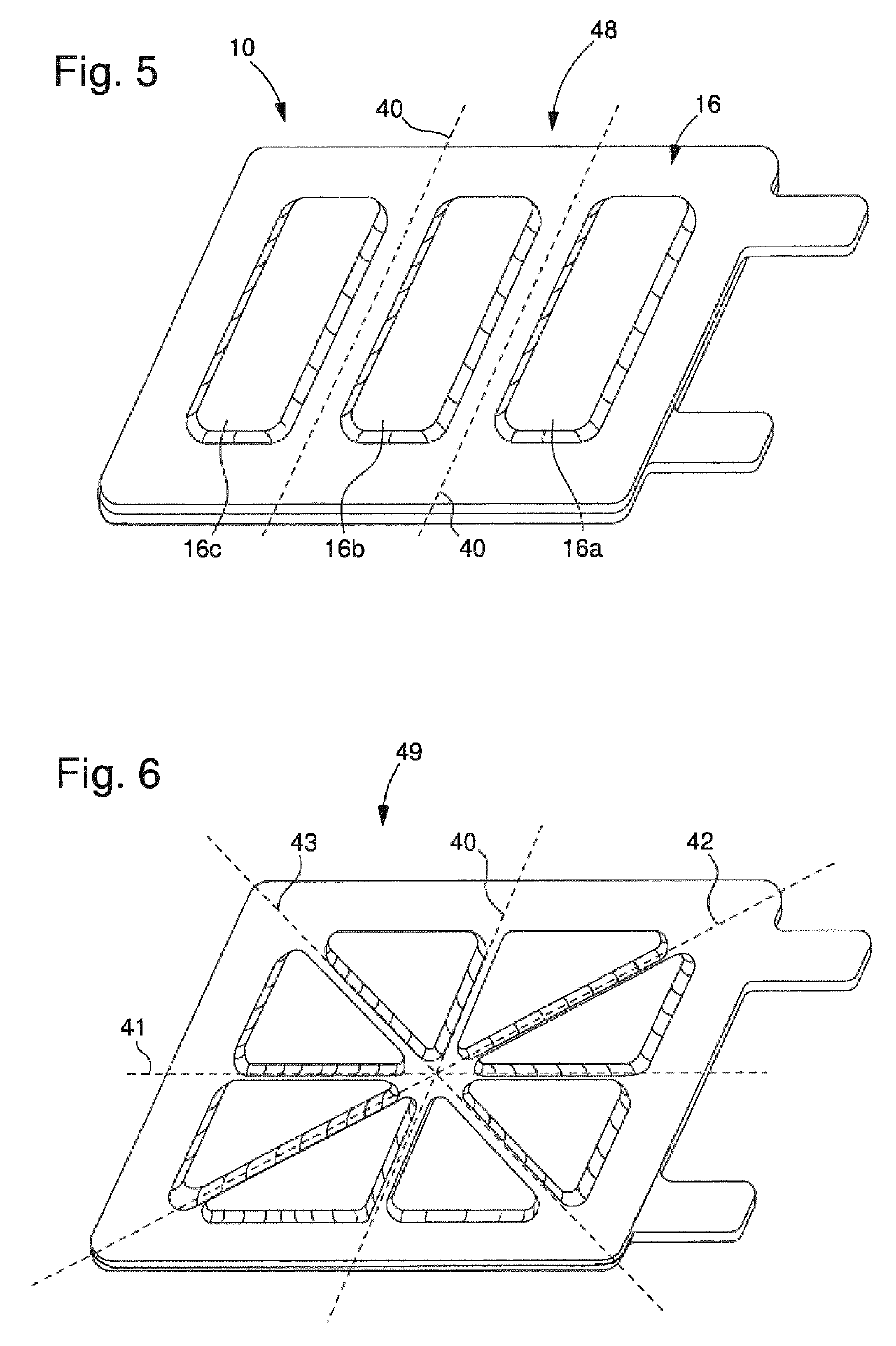
[0057]The electrochemical cell 10 as it is schematically illustrated in FIGS. 2-4 comprises a first current collector 16 and a second current collector 18. While in the perspective illustration according to FIG. 2 only the upper, first current collector 16 is illustrated, the shape and arrangement of the second or lower current collector 18 is discernible from FIGS. 3 and 4. The first current collector 16 comprises a connector tab 12 that may be integrally formed with the first current collector 16. The same may also apply to the second current collector 18 featuring an integrally formed connector tab 14.

[0058]First and second current collectors 16, 18 each comprise a collecting section 20, 30 and a connecting section 24, 34 as illustrated in FIG. 3. For instance, the first connecting section 24 of the first current collector 16 is integrally formed with the first collecting section 20. The first collecting section 20 merges into the first connecting section 24 via a first profiled ...


PUM

PropertyMeasurementUnit
distanceaaaaaaaaaa
distanceaaaaaaaaaa
distanceaaaaaaaaaa

Abstract

An electrochemical cell, including: a first current collector including a first collecting section in contact with a first electrode and including a first connecting section; a second current collector overlapping with the first current collector and including a second collecting section in contact with a second electrode and including a second connecting section; wherein the first and second current collectors are mutually connected via their first and second connecting sections and a distance between the first and second connecting sections is equal to or smaller than 50% of the distance between the first and the second collecting sections.

Description

CROSS-REFERENCE TO RELATED APPLICATIONS[0001]This is a National phase application in the United States of International Patent Application PCT / EP2014 / 054093 filed Mar. 3, 2014 which claims priority on European patent application 13168765.9 filed May 22, 2013. The entire disclosures of the above patent applications are hereby incorporated by reference.FIELD OF THE INVENTION[0002]The present invention relates to the field of electrochemical cells comprising first and second current collectors in electrical contact with respective first and second electrodes. In particular, the invention relates to thin film batteries featuring a large degree of mechanical flexibility.BACKGROUND AND PRIOR ART[0003]Among a multitude of different battery types, there exist so-called thin film batteries. Those batteries only comprise a thickness in the range of nanometers, micrometers or millimeters. They may exhibit comparatively small dimensions and are therefore generally applicable to a large spectrum...

Claims


Application Information

Patent Timeline
Patent Type & Authority Patents(United States)
IPC IPC(8): H01M10/04H01M2/02H01M4/70G04G19/00H01M50/119H01M50/133H01M50/136H01M50/55H01M50/557
CPCH01M4/70H01M2220/30H01M10/0436Y02E60/10H01M50/557H01M50/545Y02P70/50H01M50/133H01M50/136H01M50/55H01M50/119G04G19/00
Inventor HECK, PASCALSTALDER, MICHAELZUELLIG, FREDYSOHI, KUROSHLETERRIER, YVESMOLL, JERICHO LYNNLERAN, JEAN-BAPTISTEMANSON, JAN-ANDERS
Owner THE SWATCH GRP RES & DEVELONMENT LTD
Learn More