Method of injecting fuel into the combustion chamber of an internal-combustion engine running in single-fuel or multi-fuel mode

a combustion chamber and engine technology, applied in the direction of machines/engines, mechanical equipment, electric control, etc., can solve the problems of increased emissions, higher mechanical stress, fuel remains confined, and the combustion rate of these alternative fuels is lower, so as to improve the combustion even

Inactive Publication Date: 2019-05-21
INST FR DU PETROLE
View PDF20 Cites 3 Cited by
  • Summary
  • Abstract
  • Description
  • Claims
  • Application Information

AI Technical Summary

Benefits of technology

[0016]The method of the invention further improves the aforementioned drawbacks by improving the combustion even further.
[0017]The applicant has particularly developed this two-mode combustion by enabling use thereof for operation at high engine loads and / or speeds, while reducing emissions even further.
[0018]Furthermore, these combustion modes also allow reduction of the fuel consumption, to obtain a better engine behavior in transient phases (cold run or accelerations for example) while maintaining an acceptable emissions level for some pollutants (carbon monoxide, unburnt hydrocarbons).
[0020]The method can inject a liquid fuel with physicochemical characteristics allowing operation of the compression-ignition engine, such as diesel fuel, ethanol or a biofuel.

Problems solved by technology

Indeed, performance increase generally leads to an increase in emissions and to higher mechanical stress.
The problem is that the fuel remains confined in the bowl and it cannot mix with the oxidizer contained notably in the compression area, that is the volume in the upper part of the combustion chamber defined by the cylinder wall and the face of the cylinder head opposite the piston.
This involves the drawback of creating areas of high fuel richness in the combustion chamber which generate a high production of soots, carbon monoxide (CO) and unburnt hydrocarbons (HC) during combustion of this fuel mixture.
Notably, the combustion rate of these alternative fuels is lower than with more conventional fuels, which causes too slow and an incomplete combustion which generates the emission of pollutants such as unburnt hydrocarbons.

Method used


Image

  • Method of injecting fuel into the combustion chamber of an internal-combustion engine running in single-fuel or multi-fuel mode
  • Method of injecting fuel into the combustion chamber of an internal-combustion engine running in single-fuel or multi-fuel mode
  • Method of injecting fuel into the combustion chamber of an internal-combustion engine running in single-fuel or multi-fuel mode

Examples


Embodiment Construction

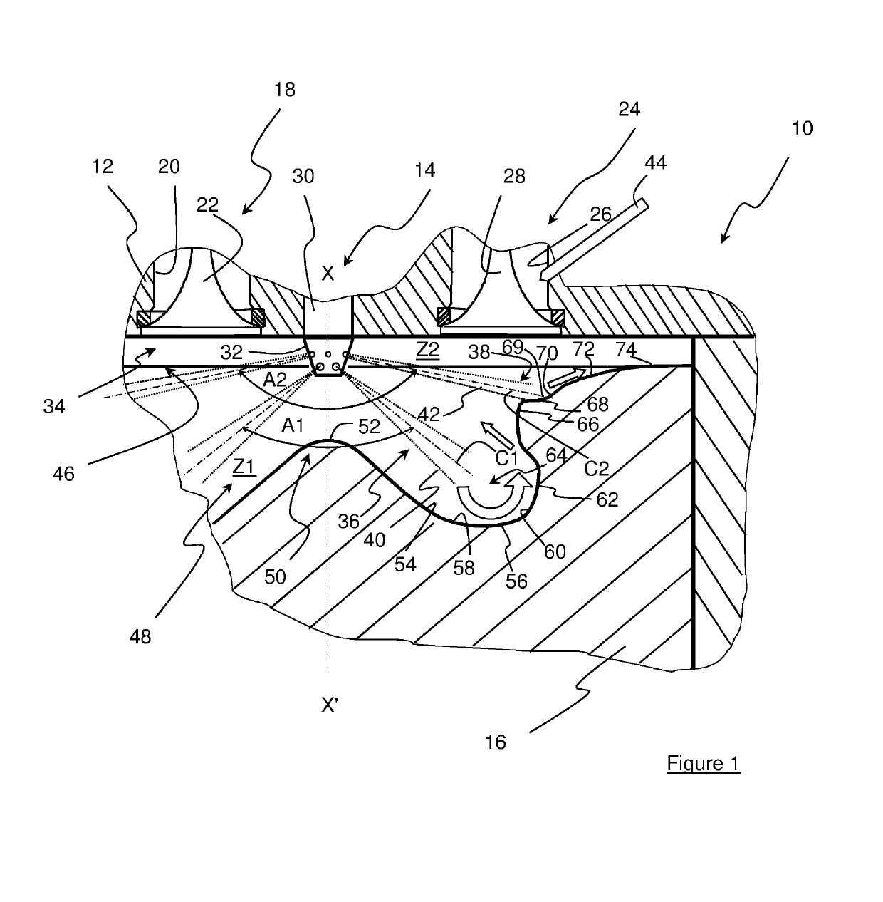
[0035]With reference to FIG. 1, a compression-ignition internal-combustion engine with direct and possibly indirect fuel injection, as illustrated by way of non-limitative example in FIG. 1, comprises at least a cylinder 10, a cylinder head 12 closing the cylinder in the upper part, direct liquid fuel (Fuel1) injection 14, gaseous or liquid fuel (Fuel2) injection and a piston 16 having an axis XX′ sliding in the cylinder with a reciprocating rectilinear motion.

[0036]In the non-limitative example of FIG. 1, indirect gaseous fuel injection 15 carried by the cylinder head are provided for fuel Fuel2.

[0037]Liquid fuel Fuel1 is understood to be a fuel such as diesel fuel, ethanol, a biofuel or any other fuel with the physicochemical characteristics allowing operation of an engine of compression-ignition type including a direct injection system for liquid fuel Fuel1.

[0038]Fuel2 can be a gaseous fuel, such as CNG (Compressed Natural Gas), LPG (Liquefied Petroleum Gas), a biogas or any othe...


PUM


Abstract

The present invention is a fuel injection method for a compression-ignition internal-combustion engine running in single-fuel or multi-fuel mode. The method, in a single-fuel mode, injects liquid fuel (Fuel1) into lower zone (Z1) and / or upper zone (Z2) of the combustion chamber and, in a multi-fuel mode, provides in the chamber mixing of an oxidizer with another fuel (Fuel2) and injection of liquid fuel (Fuel1) into lower zone (Z1) or both zones (Z1, Z2) of the combustion chamber.

Description

CROSS REFERENCE TO RELATED APPLICATIONS[0001]Reference is made to International Application No. PCT / 2015 / 055843 filed Mar. 19, 2015, and French Application No. 14 / 52.955 filed Apr. 3, 2014, which applications are incorporated herein by reference in their entirety.BACKGROUND OF THE INVENTIONField of the Invention[0002]The present invention relates to a method of injecting fuel into the combustion chamber of an internal-combustion engine, in particular a compression-ignition engine. More particularly the invention is a fuel injection method for an engine used in the aeronautic or road applications, or in the field of stationary equipments such as electrical power generators.Description of the Prior Art[0003]This type of engine generally comprises at least a cylinder, a piston provided with a projection defined in a concave bowl and which slides in the cylinder in a reciprocating rectilinear motion, an intake for an oxidizer, a burnt gas exhaust, a combustion chamber and an injection s...

Claims


Application Information

Patent Timeline
Patent Type & Authority Patents(United States)
IPC IPC(8): F02D19/06F02B43/10F02B23/06F02M61/18F02D19/10F02D41/00
CPCF02D19/0689F02B23/0669F02B23/0672F02B23/0693F02B43/10F02D19/0647F02D19/0652F02D19/10F02D41/0025F02D41/0027F02M61/182F02B23/0651Y02T10/36F02D19/0655F02D19/0692Y02T10/125Y02T10/12Y02T10/30
Inventor LAGET, OLIVIERRICHARD, STEPHANEMARTINEZ, LIONEL
Owner INST FR DU PETROLE
Why Eureka
Try Eureka