
Marine bypass system and method

a bypass system and bypass technology, applied in the field of marine vessels, can solve the problems of affecting downstream release points, restricting the transfer of on-board water, clogging, etc., and achieve the effects of reducing, eliminating, and reducing marine growth

Inactive Publication Date: 2019-05-28
HARRELSON II CLYDE WILLIS
View PDF15 Cites 0 Cited by
  • Summary
  • Abstract
  • Description
  • Claims
  • Application Information

AI Technical Summary

Benefits of technology

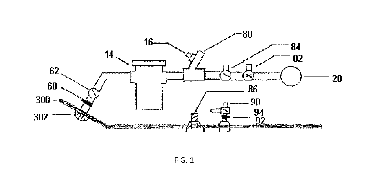
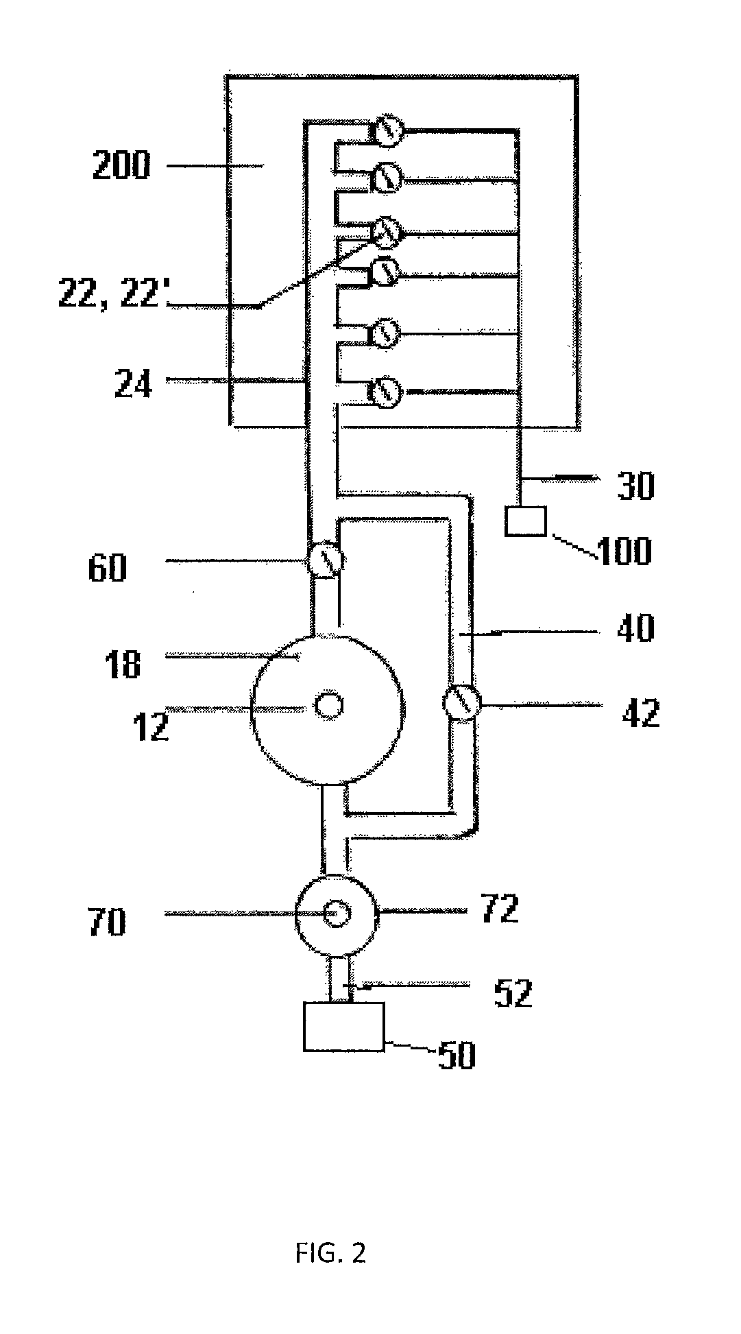
The present invention is about a better way to flush marine objects to prevent the growth of sea creatures. It is designed to be convenient, efficient, and safe for users in marine environments. The invention includes a system of primary flow channels that release water, a non-marine water supply, and secondary bypass channels that inject non-marine water around the openings to remove any sea growth.

Problems solved by technology

One common problem associated with these assemblies is marine growth, fowling, clogage, and the like.
This restriction slows the transfer of on-board water and affects downstream release points at engines, generators, air conditioners, sanitation systems, and the like.
However, conventional systems fail to efficiently and consistently provide such operation.

Method used


Image

  • Marine bypass system and method
  • Marine bypass system and method

Examples


experiment 1

[0025]Initial set-up: Series of abbreviations for mechanical units in the boat, including: PE (port engine), SE (starboard engine), G1 Generator, AC1 air conditioning unit one, AC2 air conditioning unit two on a touch screen display. Those skilled in the art having the benefit of this disclosure will recognize additional embodiments and elements useful throughout the systems and assemblies shown and described herein. Raw water intake diameters will be displayed (for instance 4″, 3″, 2.5″, 2″, 1.5″, 1″, etc.). The proper diameter was selected, the raw water diameter that corresponds to the abbreviated selected mechanical unit. A second view shows raw water intake lengths (for instance 1-10′ in six inch increments, or the like). Selection of the proper length for each raw water intake. The electronic transducer appear with corresponding identifications. Processor identifies transducers and sets a cycle, for instance ten seconds. The processor takes the information and hot water temper...


PUM

PropertyMeasurementUnit
pressuresaaaaaaaaaa
lengthsaaaaaaaaaa
temperatureaaaaaaaaaa

Abstract

Marine bypass systems and assemblies. In one embodiment, a bypass system includes a non-marine water supply injection assembly, a bypass solenoid valve, and a non-marine injector. In particular examples, the assembly comprises a heated non-marine water supply injection assembly and a non-heated, non-marine water supply injection assembly. The result is an improved device and method for enhancing the removal, and elimination, of marine growth from a marine vessel.

Description

BACKGROUNDField[0001]The present disclosure relates generally to marine vessels and, more particularly, to a marine bypass system for enhancing the reduction, or elimination, of marine growth about a water inlet.Related Art[0002]Marine vessels incorporate water inlets for a variety of onboard applications and processes. These marine inlet devices are often fully adaptable to any type of marine situation, for instance during transit and during stationary operation.[0003]One common problem associated with these assemblies is marine growth, fowling, clogage, and the like. For instance, marine vessels with cooling equipment often experience closing from marine growth, for instance in the tur-hull fittings, filters, piping, and appendages. Typically, the higher the water temperature and the faster the flow of water oxygenizes, thus creating increased marine growth. This restriction slows the transfer of on-board water and affects downstream release points at engines, generators, air cond...

Claims


Application Information

Patent Timeline
Patent Type & Authority Patents(United States)
IPC IPC(8): B63J4/00B63B59/04B01D35/28G05D7/06
CPCB63B59/04B01D35/28B63J4/00G05D7/0652
Inventor HARRELSON, II, CLYDE WILLIS
Owner HARRELSON II CLYDE WILLIS
Learn More