Asynchronous clock gating circuit

a clock gating and asynchronous technology, applied in logic circuits, power consumption reduction, pulse techniques, etc., can solve the problems of reducing the timing budget for its setup time requirement, increasing power dissipation, and additional power dissipation by the plurality of lathes

Active Publication Date: 2019-06-04
SYNOPSYS INC
View PDF3 Cites 0 Cited by
  • Summary
  • Abstract
  • Description
  • Claims
  • Application Information

AI Technical Summary

Benefits of technology

[0010]An object of the present disclosure is to provide a multi-utility asynchronous clock gating circuitry.
[0011]Yet another object of the present disclosure is to provide a multi-utility asynchronous clock gating circuitry which could be placed at the beginning of the clock network.
[0012]One more object of the present disclosure is to provide a multi-utility asynchronous clock gating circuitry that helps meet the timing requirement on the enable pin thereof.
[0013]Still a further object of the present disclosure is to provide a multi-utility asynchronous clock gating circuitry that avoids cumbersome replication of clock gating circuitry during physical implementation of the design.
[0014]Yet another object of the present disclosure is to provide a multi-utility asynchronous clock gating circuitry that helps reduce the power consumption levels in sequential circuits.SUMMARY

Problems solved by technology

Further, since clock signal are heavily loaded most of the times and this phenomenon brings about an increase in the power dissipation.
However, the drawback associated with this approach is that the additional latch based clock gating circuit when placed early in the clock tree to save clock tree power, has diminished timing budget for its setup time requirement.
This approach defeats the purpose of saving the clock tree power, additional power is dissipated by plurality of lathes itself.

Method used


Image

  • Asynchronous clock gating circuit
  • Asynchronous clock gating circuit
  • Asynchronous clock gating circuit

Examples


Embodiment Construction

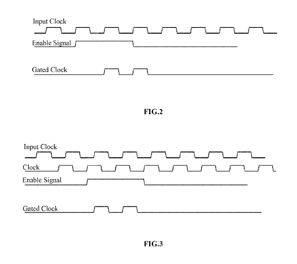
[0035]Typically, the circuit of a conventional AND gate could be designed to function as a clock gating circuit. An AND gate incorporates two inputs, namely an Enable signal, and a clock signal. The output of the AND gate depends on both the Enable signal and the clock signal. Typically, the AND gate would function only when the Enable signal is HIGH, and when the Enable signal is LOW, the clock would be gated. Hence, typically by controlling the Enable input, the AND gate is designed to function as a clock gating circuit.

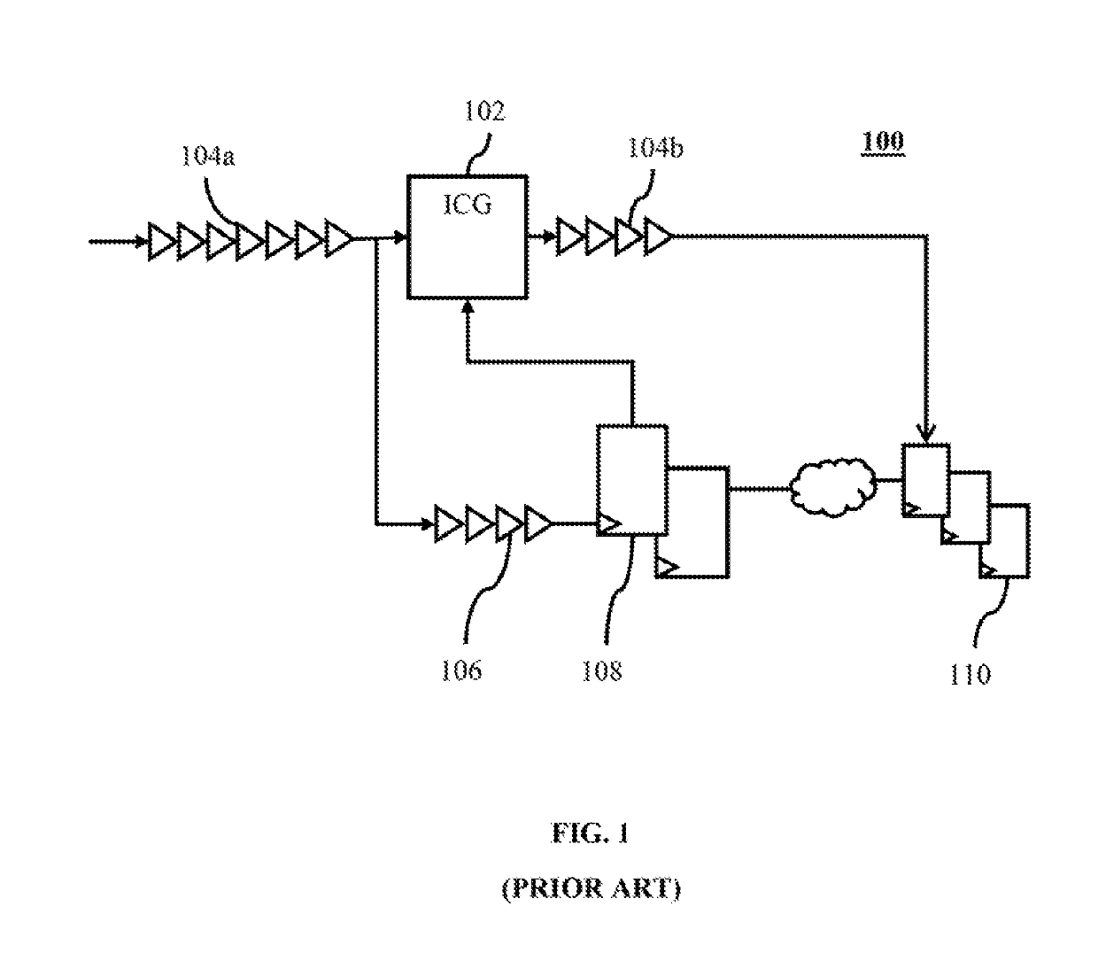
[0036]Referring to FIG. 1, there is shown a conventional (prior-art) clock network 100 of flip-flops driving an enable pin of the clock-gated circuit. As shown in FIG. 1, an integrated clock gating circuit 102 is used to reduce power consumption at the clock network by preventing individual flip-flops from switching between logic states when not in use. The integrated clock gating circuit 102 is selectively activated or inactivated based on design and implementatio...


PUM


Abstract

The present disclosure envisages an asynchronous clock gating circuitry and a method for designing the asynchronous clock gating circuitry. The asynchronous clock gating circuitry could be placed at the very beginning of the clock network, given its design and implementation logic. The asynchronous clock gating circuitry helps meet the timing requirement on the enable pin thereof. The asynchronous clock gating circuitry avoids cumbersome replication of cluck gating circuitry during physical implementation of the (circuit) design, and further helps reduce the power consumption levels in sequential circuits.

Description

CROSS REFERENCE TO RELATED APPLICATIONS[0001]This Patent Application is a National Phase Application corresponding to the PCT Application No. PCT / IN2016 / 000154 filed on Jun. 14, 2016 with the title “ASYNCHRONOUS CLOCK GATING CIRCUIT”. This Patent Application claims the priority of the Indian Provisional Patent Application No. 1276 / CHE / 2015 filed on Jun. 16, 2015 with the title “MULTI UTILITY CLOCK GATING CIRCUIT”, the contents of which are included herein by the way of reference.BACKGROUND[0002]Technical Field[0003]The present disclosure relates to electronic circuits. Particularly, the present disclosure relates to the design and implementation of integrated circuits. More particularly, the present disclosure relates to designing clock gating circuits.[0004]Description of the Related Art[0005]With the recent advancements in design and implementation of integrated electronic circuits, the emphasis has also been upon designing electronic circuits which bring about a reduction in powe...

Claims


Application Information

Patent Timeline
Patent Type & Authority Patents(United States)
IPC IPC(8): H03K3/012H03K3/037H03K19/00H03K5/135
CPCH03K3/012H03K3/037H03K19/0016H03K5/135H03K3/0375
Inventor PRAKASH, GYANKUMAR, NIDHIR
Owner SYNOPSYS INC
Why Eureka
Try Eureka