Autonomous robotic technologies for industrial inspection

a robotic technology and industrial inspection technology, applied in the direction of image enhancement, instruments, and using reradiation, can solve the problems of increasing the complexity of industrial inspections and and achieve the effect of reducing the risk of overall industrial failur

Active Publication Date: 2019-06-11
RAVENOPS INC
View PDF20 Cites 2 Cited by
  • Summary
  • Abstract
  • Description
  • Claims
  • Application Information

AI Technical Summary

Benefits of technology

[0002]The present solution provides autonomous robotic technologies for industrial inspection that can flexibly scale to meet many different types of industrial inspection. By utilizing the autonomous robotic technologies disclosed herein, increasingly large and complex industrial inspections may be completed in a fraction of the time previously required for inspections of smaller scales. Furthermore, inspections can be more comprehensive, more information about the inspected structure can be collected, and inspections can be completed more frequently—drastically decreasing the risk that an overall industrial system may fail.
[0010]According to an aspect of the disclosure, an aerial robotic device can include a first range sensor that can project at a first angle from a primary axis. The first range sensor can project towards a first plane. The aerial robotic device can also include a second range sensor that can project at a second angle from the primary axis. The second range sensor can project towards the first plane. The aerial device can also include a control system that can include at least one processor. The control system can receive a first range signal from the first range sensor. The first range signal can indicate a first distance to a wall. The control system can also receive a second range signal from the second range sensor. The second range signal can indicate a second distance to the wall. The control system can determine a difference between the first distance and the second distance. The control system can correct a gyroscope drift based on the difference between the first distance and the second distance.
[0012]The control system can determine an orientation of the wall and can correct a global yaw measurement of the aerial robotic device based on the orientation of the wall. The control system can maintain a flight path along the wall. When traveling along the flight path, the control system can orient the aerial robotic device such that the first distance to the wall is substantially equivalent to the second distance to the wall.

Problems solved by technology

By utilizing the autonomous robotic technologies disclosed herein, increasingly large and complex industrial inspections may be completed in a fraction of the time previously required for inspections of smaller scales.
For example, structures can hang from the ceiling of the industrial structure presenting obstacles not present when robotic devices fly in open spaces.

Method used


Image

  • Autonomous robotic technologies for industrial inspection
  • Autonomous robotic technologies for industrial inspection
  • Autonomous robotic technologies for industrial inspection

Examples


Embodiment Construction

[0025]The various concepts introduced above and discussed in greater detail below may be implemented in any of numerous ways, as the described concepts are not limited to any particular manner of implementation. Examples of specific implementations and applications are provided primarily for illustrative purposes.

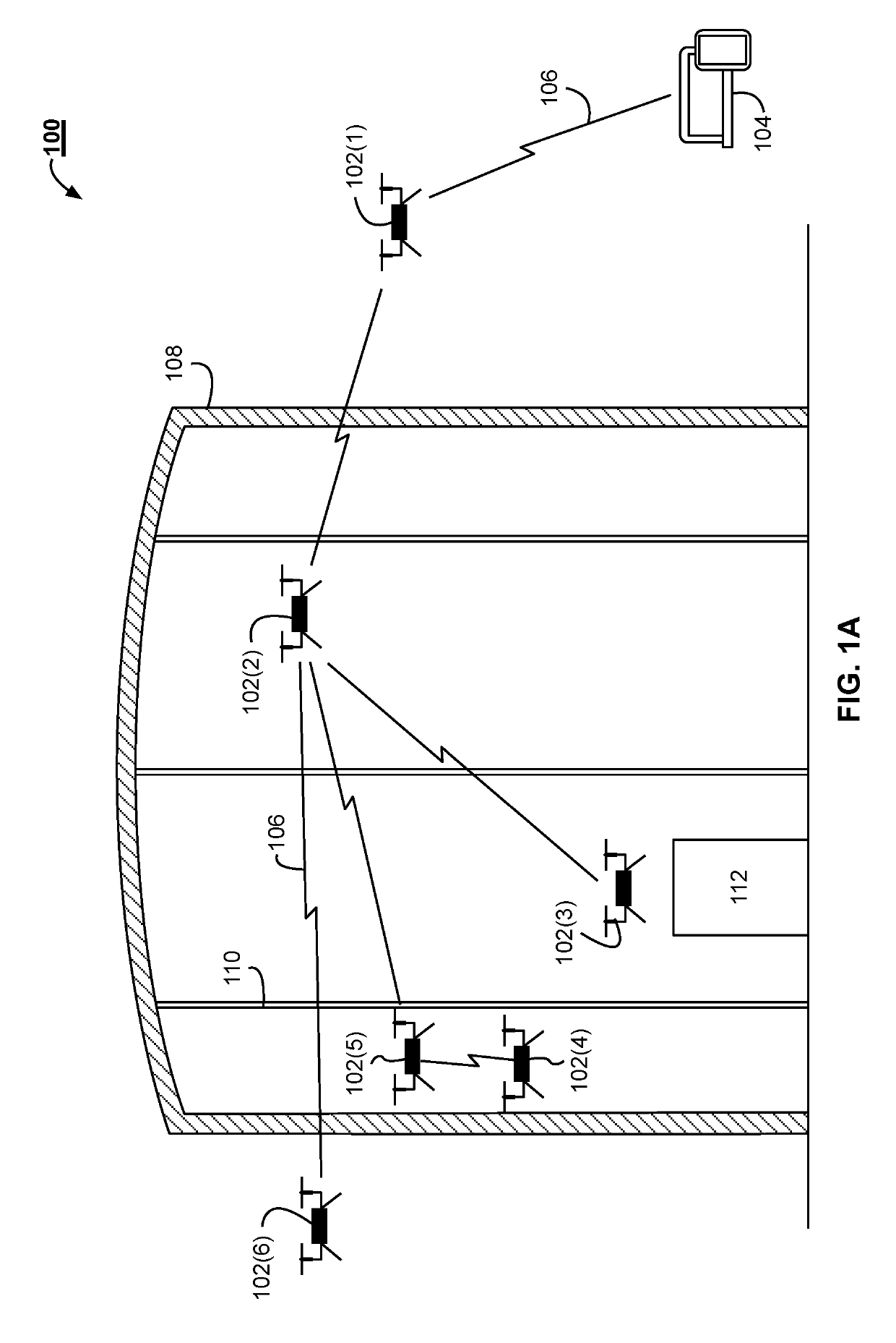
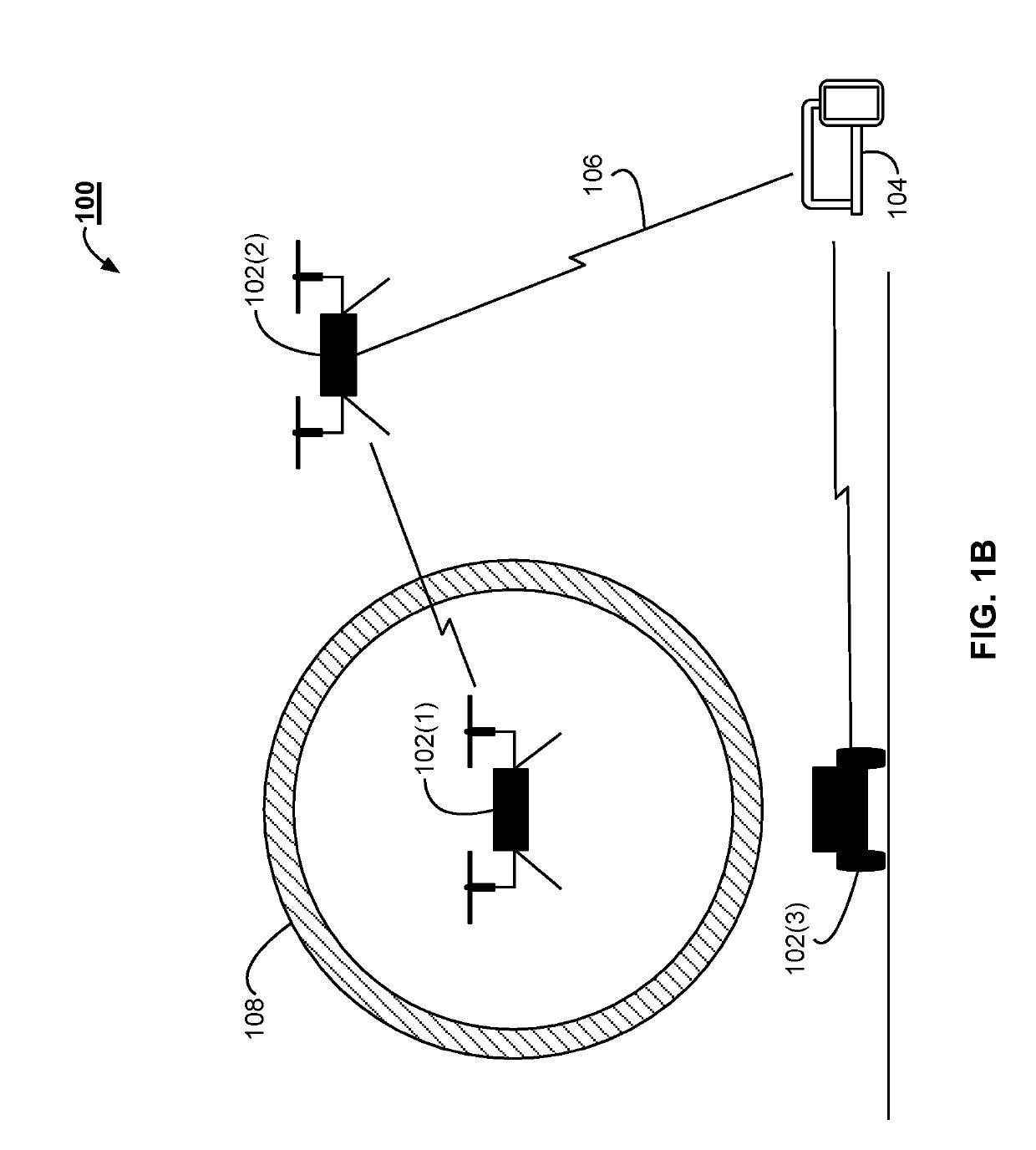
[0026]FIG. 1A illustrates an example system 100 for industrial inspection. The system 100 includes a plurality of robotic devices 102. While robotic devices 102 may be any form of robotic device, including mobile devices, stationary devices, wheeled devices, legged devices, rolling devices, crawling devices, flying devices, submersible devices, or any combination thereof, aerial robotic drones are demonstrated in the exemplary system of FIG. 1A. The robotic devices 102 may be homogeneous devices of the same type. In some implementations, the robotic devices 102 can include a heterogeneous set of devices. The heterogeneous set of devices can include different types of roboti...


PUM


Abstract

The present solution provides autonomous robotic technologies for industrial inspection that can flexibly scale to meet many different types of industrial inspection. By utilizing the autonomous robotic technologies disclosed herein, increasingly large and complex industrial inspections may be completed in a fraction of the time previously required for inspections of smaller scales.

Description

BACKGROUND OF THE DISCLOSURE[0001]The inspection of industrial equipment and infrastructure can include the examination of confined spaces, requiring “confined space entry” by humans which is time consuming, expensive, and puts the individuals performing the inspection at risk. Because of the time and expense of such manual inspection mechanisms, risk-based prioritization is often applied to an industrial inspection such that higher-risk components are inspected while lower-risk ones (which may nonetheless also fail) go uninspected, contributing to a higher probability that an overall industrial system might fail. These manual inspection processes can also face data-loss issues, as human inspectors will often only record the minimal amount of information pertinent to an inspection, such as documenting a single reading that a visual inspection was conducted, failing to capture additional information that could be useful for determining the overall risk that an industrial system might...

Claims


Application Information

Patent Timeline
Patent Type & Authority Patents(United States)
IPC IPC(8): G05D1/00G01S17/08G06T7/00B64C39/02
CPCG05D1/0088B64C39/024G01S17/08G06T7/0004G06T2207/30108B64C2201/123G06T2207/10032G05D1/0094G01S17/89G01S17/86B64U2201/00B64U2101/30B64U2201/102
Inventor OUELLETTE, JOSHUAPOST, CHARLESSHULTS, RANDALLSTONE, THOMAS
Owner RAVENOPS INC
Why Eureka
Try Eureka