Electric arc-control device

a technology of arc control device and arc control, which is applied in the direction of air-break switch, circuit-breaking switch details, high-tension/heavy-dress switch, etc., can solve the problems of breaker device, affecting the lifetime of such breaker device, and eroded electrical contacts, etc., to achieve the effect of simple and convenient operation

Active Publication Date: 2019-06-11
SOCOMEC
View PDF16 Cites 2 Cited by
  • Summary
  • Abstract
  • Description
  • Claims
  • Application Information

AI Technical Summary

Benefits of technology

[0009]Because of the presence of a folded-back switching portion, the arcing horn serves to push the arc back to the back of the breaker device, to improve splitting of the arc, and to move the arc away from the stationary contact. The movement of the arc from the stationary contact towards the arcing horn also serves to reduce erosion of the stationary contact because of limited contact between the electric arc and the stationary contact, thereby enabling the lifetime of the breaker device to be improved. The arc switching portion constitutes a sacrificial element that is consumed by the arc instead of consuming the stationary contact, thereby enabling the lifetime of the stationary contact to be improved and thus increasing the lifetime of the breaker device.
[0012]Using such an arcing horn is advantageous for reducing arc erosion both of the stationary contact and of the arcing horn since the arcing horn is made of a material that withstands arc erosion. Consequently, such a configuration makes it possible to further lengthen the lifetime of the breaker device.
[0014]Using such an arcing horn makes it possible to reduce, or even to avoid, the gas of the plasma passing laterally around it. As a result, this enables the path followed by the gas to be lengthened and thus enables the gas to be cooled better before being discharged to the outside of the breaker device. Such a configuration advantageously serves to minimize potential arcing outside the breaker device.
[0016]Such a device serves to further improve the breaking capacity of the device and thus further limit erosion of the electrical contacts due to the arc.
[0018]Such a device advantageously makes it possible to have a solution for extinguishing an electric arc that is simple and inexpensive.

Problems solved by technology

Nevertheless, a problem arises for existing breaker devices resulting from the possible erosion of electrical contacts by the electric arcs that are generated.
This erosion can affect the lifetime of such breaker devices.

Method used


Image

  • Electric arc-control device
  • Electric arc-control device
  • Electric arc-control device

Examples


Embodiment Construction

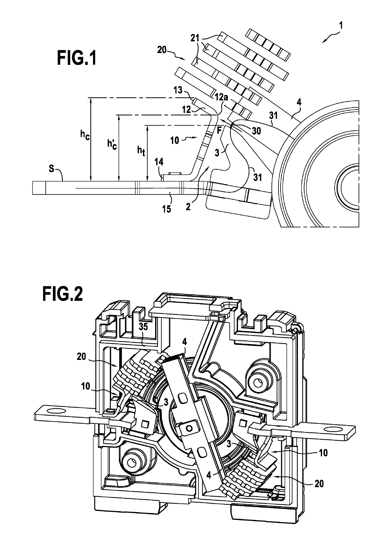
[0024]FIG. 1 shows an example of an electric arc breaker device 1 of the invention. The device shown serves to extinguish an electric arc in air. The breaker device 1 has a contact zone 2 in which there are present at least one stationary contact 3 and at least one movable contact 4 that is movable relative to the stationary contact 3. The contacts 3 and 4 can be put into contact with each other and they can be separated from each other, the movable contact 4 in the example shown being configured to perform a movement in rotation about a pivot axis when the contacts are separated. The contact head 3 and the stationary support 15 form a stationary subassembly enabling the breaker device 1 to be connected in an electrical installation. The contact head 3 may be made of metal material, e.g. of copper. When the movable contact 4 is in contact with the contact head 3, electricity can flow between these elements. When the movable contact 4 is separated from the contact head 3, electricity...


PUM


Abstract

An electric arc breaker device comprises a contact zone in which there are present at least one stationary contact and at least one movable contact that is movable relative to the stationary contact. The contacts are capable of being put into contact with each other and of being separated from each other. An arcing horn is present facing the stationary contact, the height hc of the arcing horn being greater than or equal to the height ht of the stationary contact, and the arcing horn presenting a folded-back arc switching portion extending in a direction away from the stationary contact.

Description

BACKGROUND OF THE INVENTION[0001]The invention relates to the field of electric arc breaker devices.[0002]When breaking a circuit, an electric arc is struck between electrical contacts. The arc creates a back electromotive force (emf) in the network that tends to oppose the source of the network. In an alternating current (AC) network, the magnitude of the current passing through the terminals of the breaker equipment passes periodically through zero. For example, these passages of the current through zero take place every 10 milliseconds (ms) in a 50 hertz (Hz) network. When the current passes through zero, the conductive arc cools down suddenly and the ions of the plasma of the arc then recombine. This recombination takes place more or less quickly depending on the extinction technique (splitting or lengthening), on the degree of pollution, and on the type of plasma. This recombination enables the break to withstand the network voltage that is still present at its terminals. If th...

Claims


Application Information

Patent Timeline
Patent Type & Authority Patents(United States)
IPC IPC(8): H01H9/34H01H9/46H01H73/18H01H33/08H01H33/20
CPCH01H33/20H01H9/34H01H73/18H01H33/08H01H9/46
Inventor HERTZOG, JEROME
Owner SOCOMEC
Why Eureka
Try Eureka