
Catch device and shell liner for a medical imaging apparatus

a technology for medical imaging and catch devices, applied in the field of medical devices, to achieve the effect of simple and firm connection, simple structure, and pleasing and simple appearan

Active Publication Date: 2019-07-09
SIEMENS HEALTHCARE GMBH
View PDF8 Cites 0 Cited by
  • Summary
  • Abstract
  • Description
  • Claims
  • Application Information

AI Technical Summary

Benefits of technology

[0009]The present invention provides a catch device, a shell liner, a medical imaging apparatus and a magnetic resonance imaging apparatus to achieve a simple and firm connection between apparatus shells so as to meet requirements for a pleasing appearance, convenient application and maintenance.
[0011]Furthermore, in an embodiment wherein the number of the rollers is one, the roller is sheathed in the middle of the clamping portion, and the two sides of the roller have limit structures for preventing the roller from sliding along the elastic arm.
[0013]Furthermore, in an embodiment wherein the number of the rollers is two, the rollers are symmetrically sheathed to the clamping portion, and the two sides of each roller have limit structures for preventing the roller from sliding along the elastic arm.
[0019]It can be seen from the above solution that, in the catch device and the shell liner, the medical imaging apparatus and the magnetic resonance imaging apparatus using the catch device of the present invention, at the liner of the first shell, by contacting the peripheral surface of the roller sheathed on the elastic arm with the edge of the second shell or a region adjacent to the edge of the second shell and by means of the symmetrically shaped elastic arm, the force that is applied to the elastic arm by the second shell via the roller is symmetrically applied to the elastic arm, so as to tightly catch the first shell and the second shell, while ensuring the even stress on the elastic arm and prolonging the service life of the elastic arm. Meanwhile, since the catch device is arranged in the shell liner, in view from the outer surface, the connection of the device shell has a pleasing and simple appearance. The catch device of the present invention has a simple structure, achieves a simple and firm connection between device shells, and meets requirements for a pleasing appearance and convenient application and maintenance.
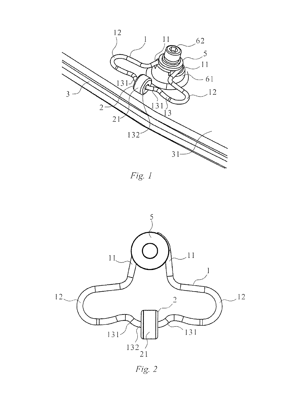
[0020]In an embodiment using one roller in the present invention, due to the limit from the limit structure, the roller can only be located in the middle of the elastic arm, and when catching the first shell and a second shell, the force applied by the second shell to the roller can be symmetrically transferred to the clamping portion and the two bending portions of the elastic arm, so as to further achieve the even stress on the elastic arm to achieve stable clamping. In this embodiment, the roller is sheathed on the straight portion, so that the roller can roll around the straight portion as the axis, thereby achieving the minimum friction between the roller and the elastic arm. The two symmetrically arranged curved portions on the one hand achieve the purpose of limiting sliding of the roller along the elastic arm, and on the other hand can transfer the force applied to the roller by the second shell to the two bending portions when the first shell and a second shell are caught, thereby achieving the even stress on the elastic arm.
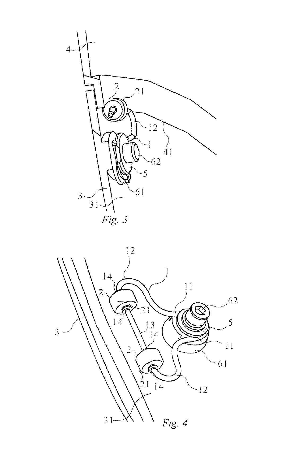
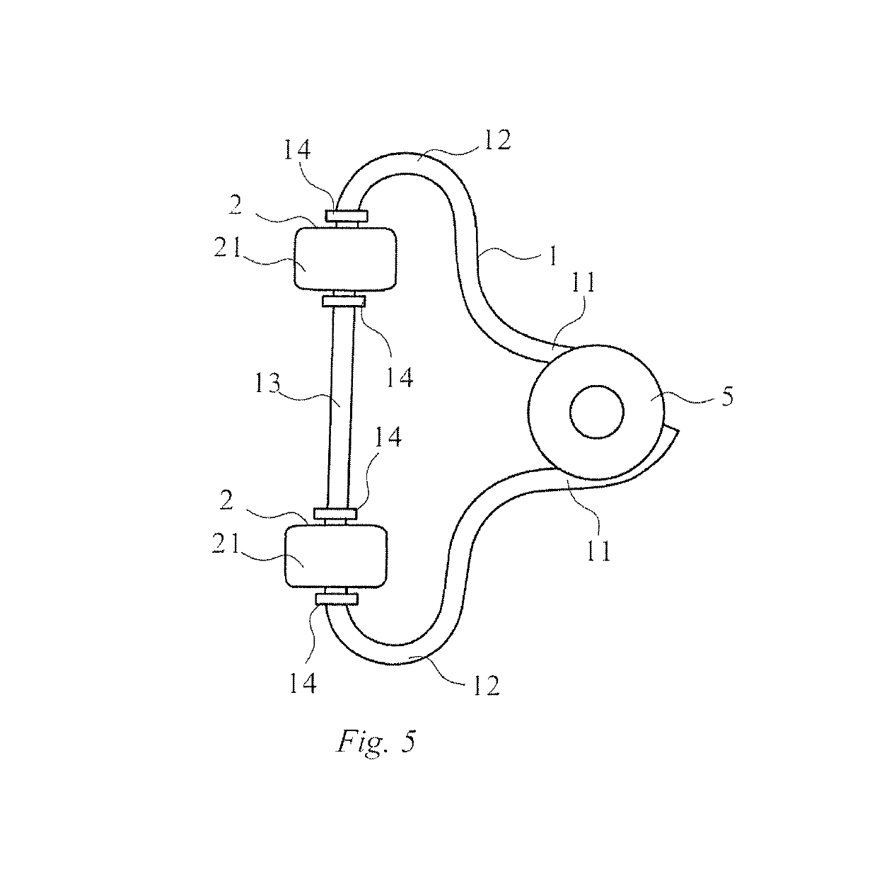
[0021]In the embodiment using two rollers in the present invention, the limit structure symmetrically limits the two rollers on the clamping portion, and when catching the first shell and a second shell, the force applied by the second shell to the two rollers can be symmetrically and uniformly transferred to the clamping portion and the two bending portions of the elastic arm, so as to further achieve the even stress on the elastic arm to achieve stable clamping. The limit structure uses a boss and / or a clasp, thereby achieving the goal of simplicity.

Problems solved by technology

Furthermore, in an embodiment wherein the number of the rollers is one, the roller is sheathed in the middle of the clamping portion, and the two sides of the roller have limit structures for preventing the roller from sliding along the elastic arm.

Method used


Image

  • Catch device and shell liner for a medical imaging apparatus
  • Catch device and shell liner for a medical imaging apparatus
  • Catch device and shell liner for a medical imaging apparatus

Examples


first embodiment

The First Embodiment

[0049]FIGS. 1-3 are structural schematic views of the first embodiment of a catch device of the present invention. As shown combined in FIGS. 1-3, the catch device of the first embodiment comprises an elastic arm 1 and a roller 2. The end portion 11 of the elastic arm 1 is fixed to the liner 31 of the first shell 3. The number of rollers 2 is one, the roller 2 is rotatably sheathed on the elastic arm 1, and the roller 2 clamps the edge 41 of the second shell 4 on the liner 31 of the first shell 3 using the elastic force of the elastic arm 1. The elastic arm 1 has two end portions 11, two bending portions 12 respectively close to the two end portions 11, and a clamping portion 13 located between the two bending portions 12, wherein the two end portions 11 are symmetrically arranged, the two bending portions 12 are symmetrically arranged, and two bending portions 12 are U-shaped with the arc portion of the U profile facing toward the outside, as shown in FIG. 2. Th...

second embodiment

The Second Embodiment

[0054]FIGS. 4-7 are structural schematic views of the second embodiment of a catch device of the present invention. As shown combined in FIGS. 4-7, the catch device of the second embodiment comprises an elastic arm 1 and a roller 2. The end portion 11 of the elastic arm 1 is fixed to the liner 31 of the first shell 3. The number of rollers 2 is two, the rollers 2 are symmetrically and rotatably sheathed on the elastic arm 1, and the two rollers 2 clamp the edge 41 of the second shell 4 on the liner 31 of the first shell 3 using the elastic force of the elastic arm 1. The elastic arm 1 has two end portions 11, two bending portions 12 respectively close to the two end portions 11, and a clamping portion 13 located between the two bending portions 12, wherein the two end portions 11 are symmetrically arranged, the two bending portions 12 are symmetrically arranged, and two bending portions 12 are U-shaped with the arc portion of the U profile facing toward the outs...


PUM


Abstract

A catch device and a shell liner for a medical imaging apparatus and a magnetic resonance imaging (MRI) apparatus that has an elastic arm, the elastic arm having a clamping portion, two bending portions located on two sides of the clamping portion and two end portions formed by extension of the ends of the two bending portions away from the clamping portion, the two end portions being used for being fixed to a liner of the first shell; and at least one roller, the roller being rotatably sheathed on the clamping portion of the elastic arm and clamping an edge of the second shell to the liner of the first shell by using an elastic force of the elastic arm, and an axial direction of the roller is parallel to the liner of the first shell and the edge of the second shell. The catch device achieves a simple and firm connection between apparatus shells, and meets requirements for a pleasing appearance and convenient application and maintenance.

Description

BACKGROUND OF THE INVENTION[0001]Field of the Invention[0002]The present invention concerns the field of medical devices, in particular to a catch device and a shell liner for use in a medical imaging apparatus such as a magnetic resonance imaging apparatus.[0003]Description of the Prior Art[0004]Magnetic Resonance Imaging (MRI) is a modern medical imaging method, including nuclear magnetic resonance. Compared with other imaging devices, such as X-ray and CT, MRI can provide better contrast between different soft tissues.[0005]The high performance and good application prospects of MRI systems promote the wide range of applications thereof, and continue to expand the market size thereof.[0006]Currently, due to considerations relating to use, a variety of medical instruments are required to be simple and clean in appearance, so it is required to use a shell to cover each component therein to isolate those components from the outside. This can prevent devices within the medical instrum...

Claims


Application Information

Patent Timeline
Patent Type & Authority Patents(United States)
IPC IPC(8): F16D41/00A61B5/055G01R33/28G01R33/38
CPCG01R33/3802G01R33/28A61B5/055A61B2560/0406
Inventor MACIEJEWSKI, BERNDPEI, JIAN HUAYOU, WEN QIANG
Owner SIEMENS HEALTHCARE GMBH
Learn More