Engine system and control method for engine system

a technology of engine system and control method, which is applied in the direction of electric control, machine/engine, charge feed system, etc., can solve the problems of excessive increase in fuel injection amount, rich imbalance, and overheating of the catalyst of the exhaust gas control apparatus attached to the exhaust system, so as to suppress the imbalance degree and reduce the imbalance degree

Inactive Publication Date: 2019-07-09
TOYOTA JIDOSHA KK
View PDF12 Cites 0 Cited by
  • Summary
  • Abstract
  • Description
  • Claims
  • Application Information

AI Technical Summary

Benefits of technology

[0005]The disclosure provides an engine system and a control method for an engine system with which it is possible to further restrain a catalyst of an exhaust gas control apparatus attached to an exhaust system from being overheated when there is a lean imbalance in port injection and to further suppress an imbalance.
[0007]With the engine system according to the first aspect of the disclosure, operation control of the engine is performed while the injection ratio between the fuel injection in which the in-cylinder injection valve is used and the fuel injection in which the port injection valve is used is adjusted based on the operation state of the engine. In addition, the imbalance determination of determining whether there is the rich imbalance where the fuel injection amount with respect to any of the cylinders is larger than the fuel injection amount with respect to the other of the cylinders and determining whether there is the lean imbalance where the fuel injection amount with respect to any of the cylinders is smaller than the fuel injection amount with respect to the other of the cylinders is performed based on any of the variation in air-fuel ratio and the rotational variation of the engine with respect to the fuel injection in which the in-cylinder injection valve is used and the fuel injection in which the port injection valve is used. When the electronic control unit determines that there is the lean imbalance with respect to the fuel injection in which the port injection valve is used in the imbalance determination, the first fuel injection region in which the port injection valve is used is changed to the second fuel injection region in which the in-cylinder injection valve is used. Accordingly, it is possible to further suppress an imbalance that occurs when fuel is injected from the port injection valve in the first fuel injection region in which the port injection valve is used, and to further restrain a catalyst of the exhaust gas control apparatus from being overheated. That is, it is possible to further suppress the imbalance while further restraining the catalyst of the exhaust gas control apparatus from being overheated.
[0008]In the engine system, the electronic control unit may be configured to perform the fuel injection from the in-cylinder injection valve at a fuel injection timing at which the engine is unlikely to misfire when the electronic control unit changes the region of fuel injection from the first fuel injection region to the second fuel injection region and operates the engine. The first fuel injection region in which the port injection valve is used is a region in which operating the engine with fuel being injected from the port injection valve is advantageous in terms of fuel efficiency and stability in comparison with operating the engine with fuel being injected from the in-cylinder injection valve. Therefore, according to the first aspect of the disclosure, since the fuel is injected from the in-cylinder injection valve at the fuel injection timing at which the engine is unlikely to misfire when the engine is operated after the first fuel injection region in which the port injection valve is used is changed to the second fuel injection region in which the in-cylinder injection valve is used, a decrease in fuel efficiency and stability caused by switching to the second fuel injection region in which the in-cylinder injection valve is used can be further suppressed. Here, the meaning of the expression “fuel injection timing at which misfire is unlikely to occur” may include a fuel injection timing with the lowest possibility of misfire obtained by an experiment or the like, a fuel injection timing close to such a fuel injection timing, and a fuel injection timing at which stable explosive combustion can be achieved.
[0010]In the engine system, the electronic control unit may be configured to change the region of fuel injection back to the first fuel injection region from the second fuel injection region when the electronic control unit determines that the lean imbalance is occurred with respect to the fuel injection in which the in-cylinder injection valve is used after the first fuel injection region. In many general engines, when the lean imbalance occurs with respect to both of the fuel injection in which the port injection valve is used and the fuel injection in which the in-cylinder injection valve is used, the degree of the lean imbalance with respect to the fuel injection in which the port injection valve is used is smaller than the degree of the lean imbalance with respect to the fuel injection in which the in-cylinder injection valve is used. Therefore, according to the first aspect of the disclosure, since the region of fuel injection changed to the second fuel injection region in which the in-cylinder injection valve is used is changed back to the first fuel injection region in which the port injection valve is used when the electronic control unit determines that there is the lean imbalance with respect to the fuel injection in which the in-cylinder injection valve is used after the first fuel injection region in which the port injection valve is used is changed to the second fuel injection region in which the in-cylinder injection valve is used, it is possible to reduce the degree of the imbalance.
[0011]In the engine system, the electronic control unit may be configured to perform the fuel injection from the port injection valve at a fuel injection timing at which the engine is unlikely to misfire when the electronic control unit changes the region of fuel injection back to the first fuel injection region from the second fuel injection region and operates the engine. According to the first aspect of the disclosure, it is possible to further suppress the degree of the imbalance. Here, the meaning of the expression “fuel injection timing at which misfire is unlikely to occur” may include a fuel injection timing with the lowest possibility of misfire obtained by an experiment or the like, a fuel injection timing close to such a fuel injection timing, and a fuel injection timing at which stable explosive combustion can be achieved.

Problems solved by technology

However, in the engine system, in a case where an imbalance is appropriately corrected by increasing the fuel injection time when there is a lean imbalance where the fuel injection amount with respect to any of a plurality of cylinders is smaller than the fuel injection amount with respect other cylinders, a catalyst of an exhaust gas control apparatus attached to an exhaust system may be overheated if the degree of imbalance is relatively large.
In order to further restrain the catalyst from being overheated, it is needed to individually increase the fuel injection amount with respect to the cylinders but the increase in fuel injection amount becomes excessive.
The rich imbalance is an imbalance in which a fuel injection amount with respect to any of the cylinders is larger than a fuel injection amount with respect to the other of the cylinders.
The lean imbalance is an imbalance in which a fuel injection amount with respect to any of the cylinders is smaller than a fuel injection amount with respect to the other of the cylinders.
In addition, the imbalance determination of determining whether there is the rich imbalance where the fuel injection amount with respect to any of the cylinders is larger than the fuel injection amount with respect to the other of the cylinders and determining whether there is the lean imbalance where the fuel injection amount with respect to any of the cylinders is smaller than the fuel injection amount with respect to the other of the cylinders is performed based on any of the variation in air-fuel ratio and the rotational variation of the engine with respect to the fuel injection in which the in-cylinder injection valve is used and the fuel injection in which the port injection valve is used.
The rich imbalance is an imbalance in which a fuel injection amount with respect to any of the cylinders is larger than a fuel injection amount with respect to the other of the cylinders.
The lean imbalance is an imbalance in which a fuel injection amount with respect to any of the cylinders is smaller than a fuel injection amount with respect to the other of the cylinders.

Method used


Image

  • Engine system and control method for engine system
  • Engine system and control method for engine system
  • Engine system and control method for engine system

Examples


Embodiment Construction

[0019]Hereinafter, an embodiment of the disclosure will be described by using an example.

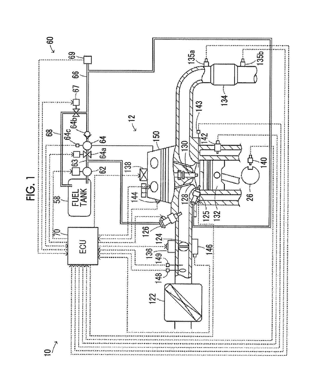
[0020]FIG. 1 is a configuration view schematically illustrating a configuration of an engine system 10 in an example of the disclosure. As illustrated in FIG. 1, the engine system 10 in the example is provided with an engine 12, a fuel supply device 60, and an electronic control unit (hereinafter, will be referred to as “ECU”) 70 that performs operation control of the engine 12. The engine system 10 is installed in an automobile that travels by using power from the engine 12 alone or a hybrid automobile that travels by using power from the engine 12 and a motor (not shown).

[0021]The engine 12 is configured as an internal-combustion engine that includes a plurality of cylinders (for example, four cylinders, six cylinders, eight cylinders, or the like) and outputs power by using fuel, such as gasoline or gas oil. As illustrated in FIG. 1, the engine 12 includes an in-cylinder injection valve 125 t...


PUM


Abstract

An engine system includes an engine that, a fuel supply device, and an electronic control unit. The electronic control unit is configured to control the fuel supply device and to perform operation control of the engine by adjusting an injection ratio between fuel injection from an in-cylinder injection valve and a port injection valve according to the operation state of the engine. The electronic control unit is configured to perform imbalance determination. The electronic control unit is configured to change a region of fuel injection from a first fuel injection region to a second fuel injection region when the electronic control unit determines that a lean imbalance is occurred with respect to the fuel injection in which the fuel injection from the port injection valve is performed.

Description

INCORPORATION BY REFERENCE[0001]The disclosure of Japanese Patent Application No. 2017-002456 filed on Jan. 11, 2017 including the specification, drawings and abstract is incorporated herein by reference in its entirety.BACKGROUND1. Technical Field[0002]The disclosure relates to an engine system and a control method for an engine system. Specifically, the disclosure relates to an engine system provided with a multi-cylinder engine that includes an in-cylinder injection valve injecting fuel into a cylinder and a port injection valve injecting fuel into an intake port and a control method for an engine system.2. Description of Related Art[0003]In the related art, as an engine system provided with a multi-cylinder engine that includes an in-cylinder injection valve and a port injection valve, there is proposed an engine system in which a process of offsetting an imbalance is performed when there is an unevenness abnormality (imbalance) between cylinders caused by fuel injection (refer ...

Claims


Application Information

Patent Timeline
Patent Type & Authority Patents(United States)
IPC IPC(8): F02D41/30F02M37/18F02D35/02F02D41/14
CPCF02D41/3082F02D35/023F02M37/18F02D41/3094F02D2200/0602F02D41/1454F02D41/0085F02D41/0235F02D41/22F02D2041/0265F02D2041/224
Inventor GENKO, TAKESHIANDO, DAIGOWATANABE, CHISAKONDO, SHINYANISHIGAKI, TAKAHIRO
Owner TOYOTA JIDOSHA KK
Why Eureka
Try Eureka