

Method and circuit for detecting a short circuit of a resolver exciter line to ground or to the operating voltage
a short circuit and exciter line technology, applied in short-circuit testing, converting sensor output electrical/magnetically, instruments, etc., can solve problems such as inadequate diagnosis, and achieve the effect of fast diagnosis and easy detection
- Summary
- Abstract
- Description
- Claims
- Application Information
AI Technical Summary
Benefits of technology
Problems solved by technology
Method used
Image

Examples
Embodiment Construction
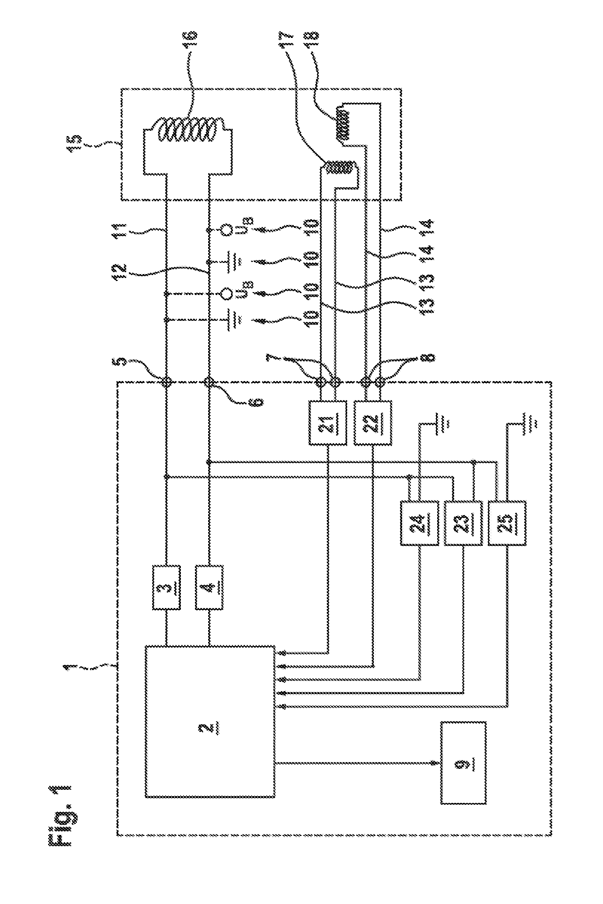
[0019]In FIG. 1, the control apparatus 1 for the resolver 15 is in the center, said control apparatus being able to be integrated into the control device for a vehicle (not depicted here). It has a processor 2 (or uses it as well) that monitors the correct operation of all the resolver functions to be controlled and also displays malfunctions if need be.
[0020]The control apparatus 1 controls particularly the power stages 3 and 4 for providing the sinusoidal excitation signal for the field coil 16 of the resolver 15 at the first connections 5 and 6. At the second connections 7 and 8, the signals of the sine coil 17 and the cosine coil 18, which represent the instantaneous angular position of the measurement object (e.g. the shaft of the motor), arrive at the control apparatus 1 and, following conversion in the AD converters 21 and 22, can be processed further as a digital signal by software.
[0021]The resolver excitation lines 11 and 12 are the connection from the first connections 5 ...
PUM
 Abstract
Description
Claims
Application Information