Method for collective calibration of multiple vehicle safety system sensors

Active Publication Date: 2019-07-30
HUNTER ENG
View PDF7 Cites 1 Cited by
  • Summary
  • Abstract
  • Description
  • Claims
  • Application Information

AI Technical Summary

Benefits of technology

[0008]In one embodiment, a method of the present invention transforms one or more fused tracks associated with the spatial position and movement of objects or features observed in an external environment surrounding a vehicle from a vehicle-centric spatial frame of reference, such as associated with a vehicle body or centerline, into a vehicle movement spatial frame of reference associated with a vehicle wheel assembly orientation, such as a vehicle thrust line or vehicle thrust angle. Initially, the vehicle thrust line or vehicle thrust angle is determined relative to the vehicle centerline via a wheel alignment measurement process and a representation thereof stored in an onboard data store accessible by the primary vehicle sensor control system. During vehicle operation, as external objects are observed and tracked by individual onboard vehicle sensors, the primary vehicle sensor control system receives the tracking data from the individual onboard vehicle sensors, and establishes associated fused tracks for the external objects within a common spatial frame of reference associated with the vehicle body or centerline. Each fused track is further transformed by the primary vehicle sensor control system into a spatial frame of reference associated with an actual straight-line movement direction of the vehicle by adjusting for an identified deviation between the determined vehicle thrust line or thrust axis contained in the onboard data store, and the vehicle body or centerline, ensuring that each fused track associated with an object external to the vehicle accurately represents the relative spatial relationships and movements between the object and the moving vehicle.
[0009]In a further method of the present disclosure, the stored representation of the vehicle thrust line or vehicle thrust angle accessible by the primary vehicle sensor control system is updated or revised in ...

Problems solved by technology

Such a change may result inadvertently from changes in the vehicle suspension system occurring over time, or may ...

Method used


Image

  • Method for collective calibration of multiple vehicle safety system sensors
  • Method for collective calibration of multiple vehicle safety system sensors
  • Method for collective calibration of multiple vehicle safety system sensors

Examples


Embodiment Construction

[0020]The following detailed description illustrates the invention by way of example and not by way of limitation. The description enables one skilled in the art to make and use the present disclosure, and describes several embodiments, adaptations, variations, alternatives, and uses of the present disclosure, including what is presently believed to be the best mode of carrying out the present disclosure.

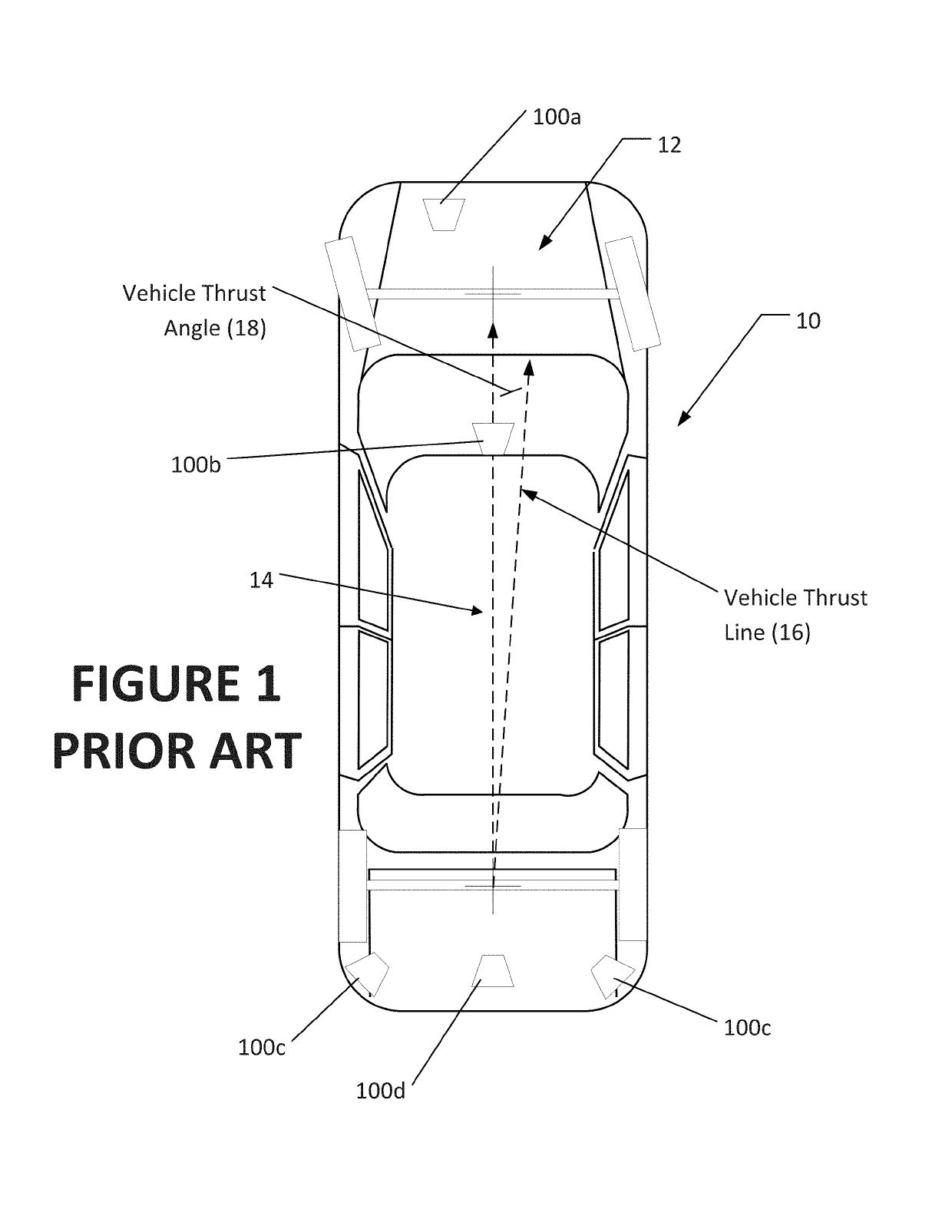
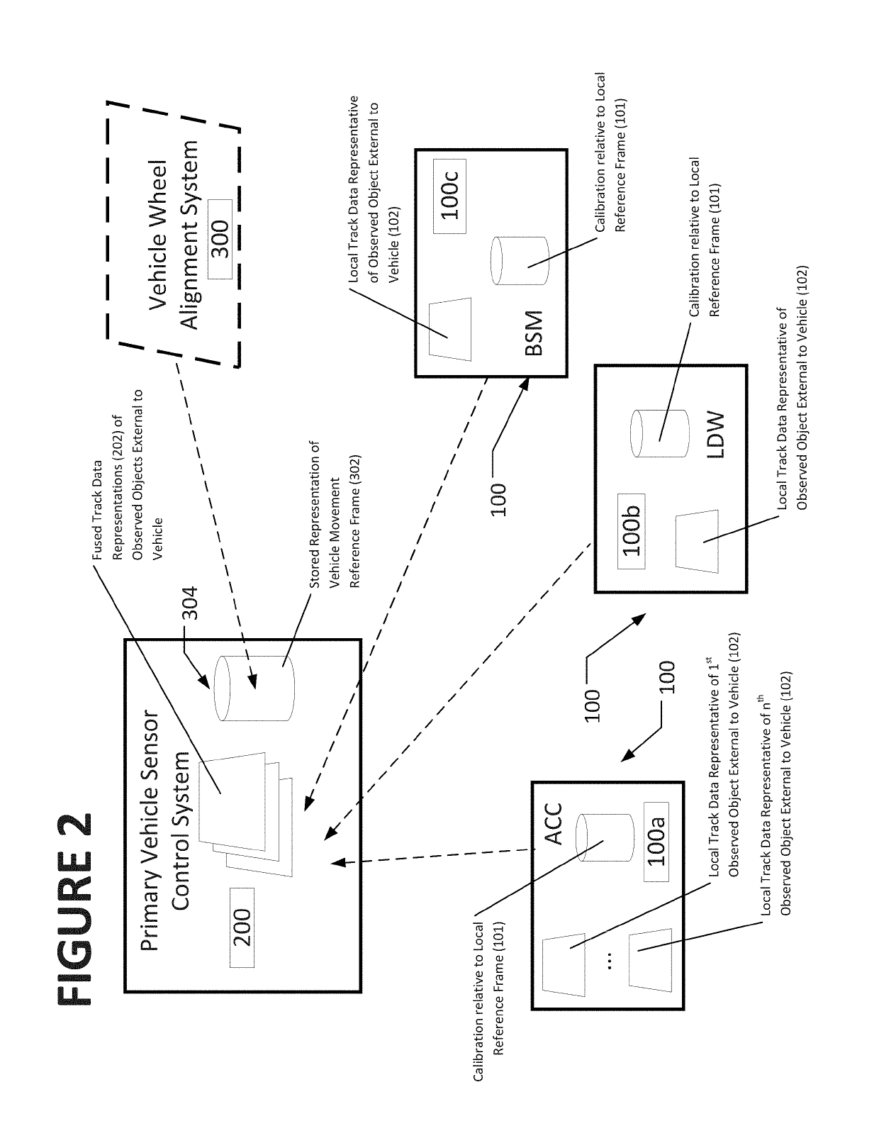
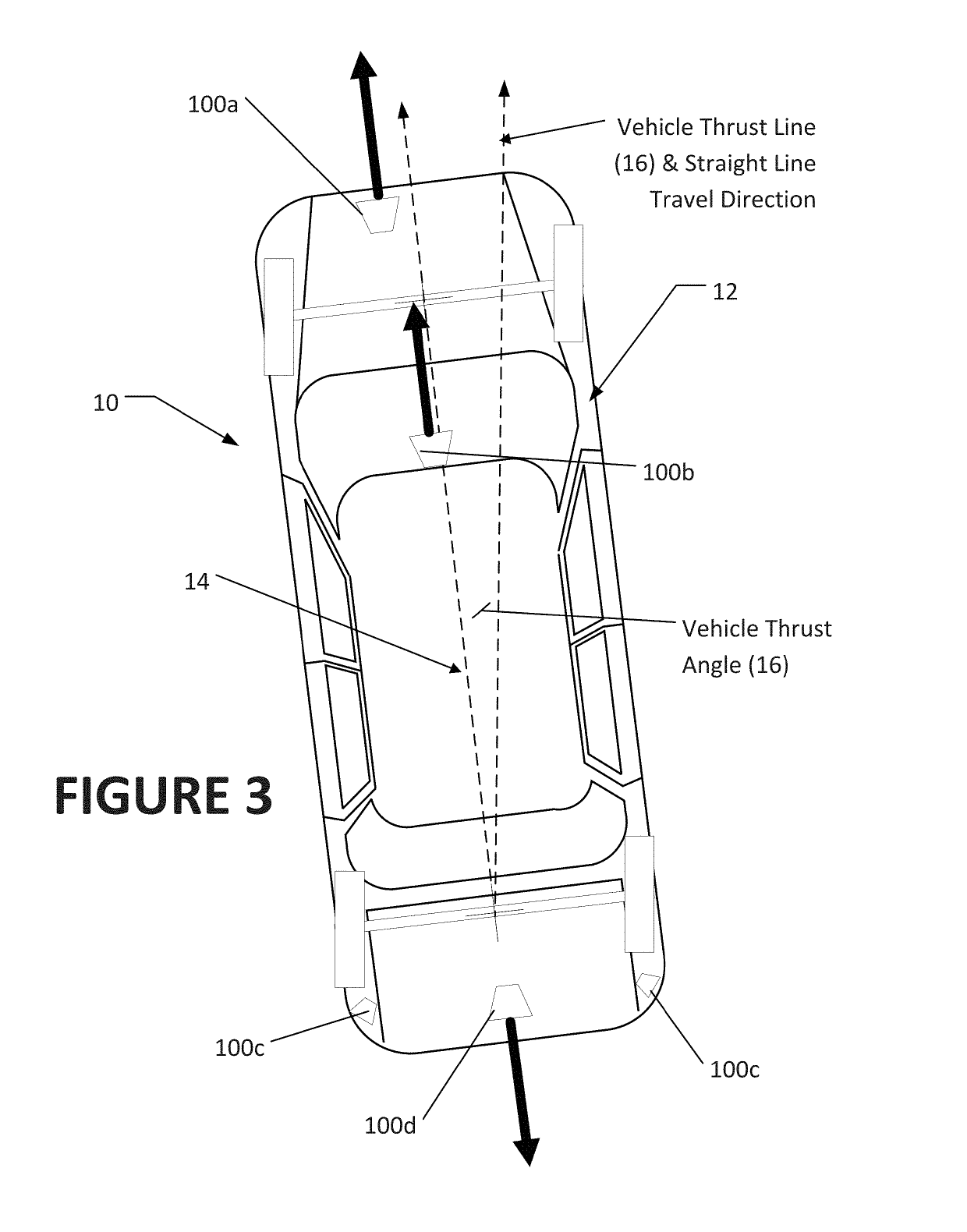
[0021]With reference to the several figures, and to FIG. 1 in particular, a vehicle 10 is shown in which one or more onboard sensor systems 100 are configured to observe the external environment in proximity to the vehicle in order to detect the presence of objects or features. These onboard sensor systems may include, but are not limited to, adaptive cruise control (ACC) sensors 100a, lane departure warning (LDW) sensors (100b), blind spot monitoring sensors (100c), and backup cameras (100d). Each onboard sensor system 100 is calibrated (shown by 101) according to manufacture guide...


PUM


Abstract

A method for transforming track representations associated with a spatial position and movement of objects or features observed in an external environment surrounding a vehicle from a vehicle-centric spatial frame of reference, such as associated with a vehicle body or centerline, into a common vehicle movement spatial frame of reference such as may be associated with a vehicle thrust line or vehicle thrust angle.

Description

CROSS-REFERENCE TO RELATED APPLICATIONS[0001]The present application is related to, and claims priority from, U.S. Provisional Application Ser. No. 62 / 325,884 filed on Apr. 21, 2016, and which is herein incorporated by reference.STATEMENT REGARDING FEDERALLY SPONSORED RESEARCH[0002]Not Applicable.BACKGROUND OF THE INVENTION[0003]The present application is related generally to onboard vehicle safety and monitoring systems configured to observe the environment surrounding the vehicle, and in particular, to the calibration of tracking data obtained from multiple onboard sensor systems into fused tracks for external objects relative to a determined axis or line associated with movement of the vehicle, ensuring that external objects observed by the multiple onboard sensors are interpreted as having cohesive spatial tracks relative to the moving vehicle, and enabling comprehensive and consistent situational awareness by the onboard vehicle safety systems.[0004]Onboard vehicle safety syste...

Claims


Application Information

Patent Timeline
IPC IPC(8): G07C5/00G01S17/93G01S7/497G01S13/931G01S17/86G01S17/931
CPCG01S7/497G07C5/008G01S17/936G01S7/4972G01S13/931G01S17/66G01S17/50G01S7/4026G01S17/86G01S17/931G07C5/0808G07C5/0816
Inventor COLARELLI, III, NICHOLAS J.STREGE, TIMOTHY A.
Owner HUNTER ENG
Why Eureka
Try Eureka