
3-D printed/manufactured suppressor element

a suppressor element and printed technology, applied in the field of printed suppressor elements, can solve the problems of high heat signature, high heat signature of known suppressors, and inability to efficiently dissipate heat, and achieve the effect of reducing heat signatur

Active Publication Date: 2019-08-06
OGLESBY PAUL A
View PDF45 Cites 11 Cited by
  • Summary
  • Abstract
  • Description
  • Claims
  • Application Information

AI Technical Summary

Benefits of technology

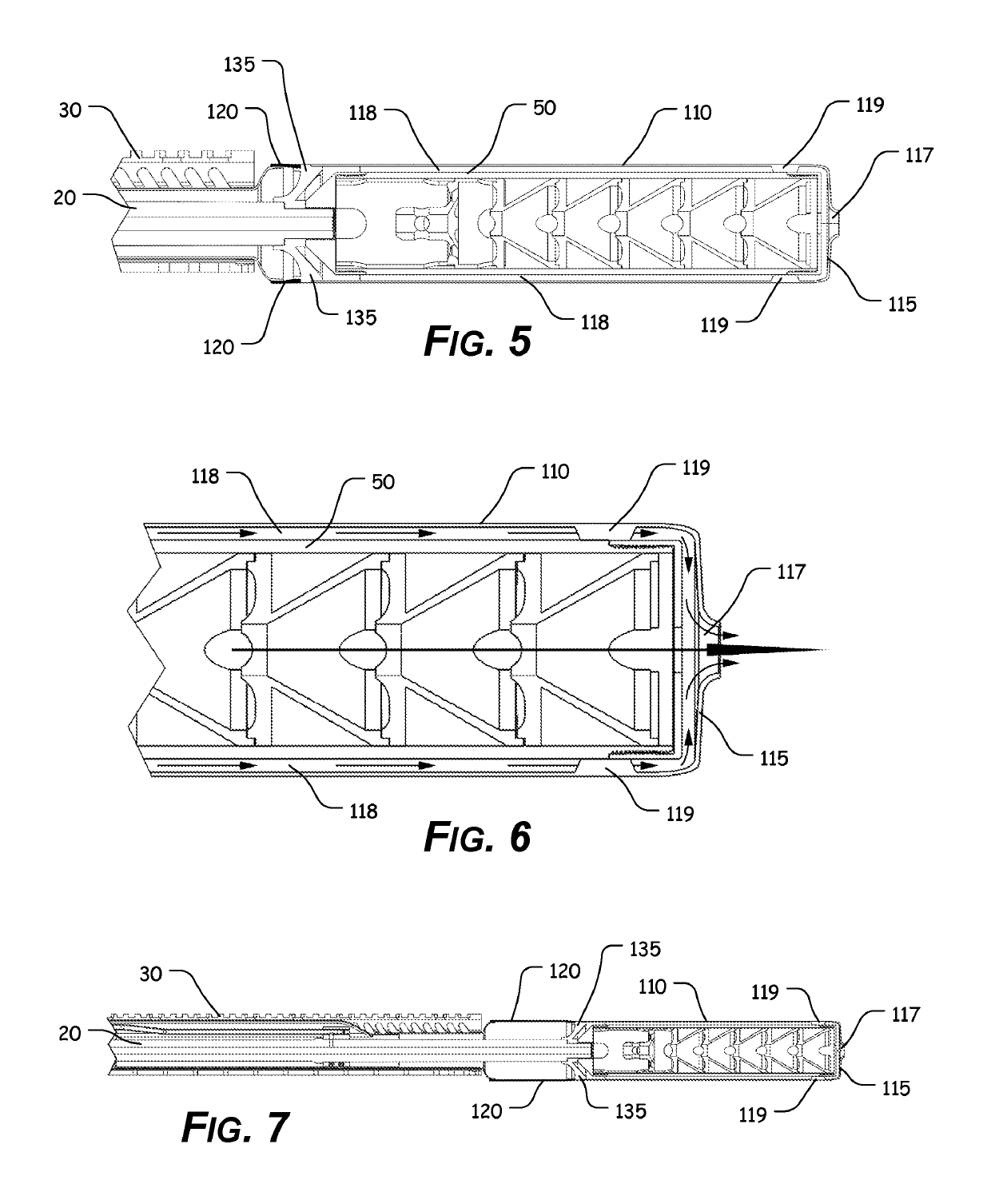
The solution effectively reduces the heat signature of the suppressor, providing improved cooling and protection by drawing in ambient air to dissipate heat efficiently during firing cycles.

Problems solved by technology

Unfortunately, heat is created during a firearm firing sequence and any attached suppressor can become extremely hot during the firing sequence.
Known suppressors can produce an extremely high heat signature and are not often efficient in dissipating heat, particularly if a fabric cover is placed over the suppressor to reduce the heat signature of the suppressor or protect the user from being burned by the suppressor.

Method used


Image

  • 3-D printed/manufactured suppressor element
  • 3-D printed/manufactured suppressor element
  • 3-D printed/manufactured suppressor element

Examples


Embodiment Construction

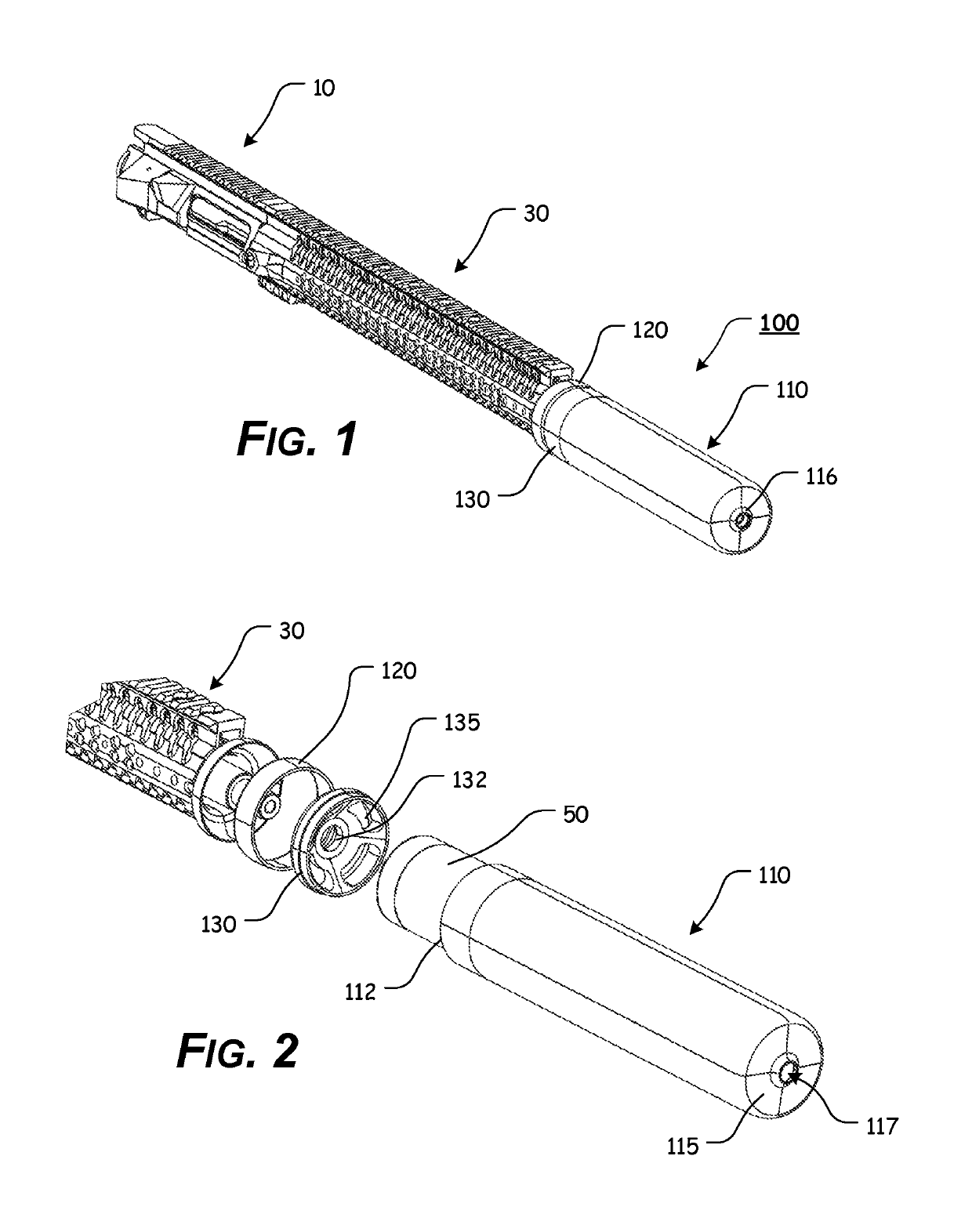
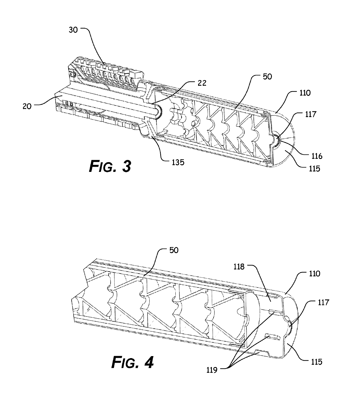
[0063]For simplicity and clarification, the design factors and operating principles of the 3-D printed suppressor element according to the present disclosure are explained with reference to various exemplary embodiments of a 3-D printed suppressor element according to the present disclosure. The basic explanation of the design factors and operating principles of the 3-D printed suppressor element is applicable for the understanding, design, and operation of the present disclosure. It should be appreciated that the present disclosure can be adapted to many applications where heat shielding and / or thermal venting can be used.

[0064]As used herein, the word “may” is meant to convey a permissive sense (i.e., meaning “having the potential to”), rather than a mandatory sense (i.e., meaning “must”). Unless stated otherwise, terms such as “first” and “second” are used to arbitrarily distinguish between the elements such terms describe. Thus, these terms are not necessarily intended to indica...


PUM


Abstract

A suppressor element having at least some of a body portion having a body cavity defined therein; a shielding portion, wherein the shielding portion is positioned over at least a portion of the body portion, such that a venting cavity is defined between at least a portion of the body portion and at least a portion of the shielding portion; one or more support elements that extend between the body portion and the shielding portion; and a rear cap that extends from a body portion first end, wherein the rear cap includes a mounting aperture, wherein the mounting aperture allows the rear cap to be attached or coupled to a barrel or muzzle device of a firearm, and wherein at least the body portion, the shielding portion, and the one or more support elements, are formed as an integral or monolithic unit.

Description

ACROSS-REFERENCE TO RELATED APPLICATIONS[0001]This patent application is a continuation of U.S. patent application Ser. No. 15 / 405,873, filed Jan. 13, 2017, which is a continuation-in-part of U.S. patent application Ser. No. 14 / 881,368, filed Oct. 13, 2015, which claims the benefit of U.S. Patent Application Ser. No. 62 / 063,197, filed Oct. 13, 2014, the disclosures of which are incorporated herein by reference in their entireties.STATEMENT REGARDING FEDERALLY SPONSORED RESEARCH OR DEVELOPMENT[0002]Not Applicable.REFERENCE TO SEQUENCE LISTING, A TABLE, OR A COMPUTER PROGRAM LISTING COMPACT DISC APPENDIX[0003]Not Applicable.NOTICE OF COPYRIGHTED MATERIAL[0004]The disclosure of this patent document contains material that is subject to copyright protection. The copyright owner has no objection to the reproduction by anyone of the patent document or the patent disclosure, as it appears in the Patent and Trademark Office patent file or records, but otherwise reserves all copyright rights ...

Claims


Application Information

Patent Timeline
Patent Type & Authority Patents(United States)
IPC IPC(8): F41A21/30
CPCF41A21/30
Inventor OGLESBY, PAUL A.
Owner OGLESBY PAUL A
Learn More