Vector compression system

a compression system and valve technology, applied in the field of surgical bone fixation technology, can solve the problems of high relative movement of bone fragments, inability to provide significant compression, and inability to achieve significant compression, and achieve the effect of high suture tension

Active Publication Date: 2019-08-20
KINAMED
View PDF36 Cites 0 Cited by
  • Summary
  • Abstract
  • Description
  • Claims
  • Application Information

AI Technical Summary

Benefits of technology

[0010]All of these methods described above have shortcomings despite their clinical usefulness. Metal fixation devices generally suffer from a mismatch in elasticity between the device and the bone that a device is compressing. This can result in a loss of compression with very minor amounts of bone resorption or device stretching. Nails, screws, wire, and plates are all typically prone to fatigue-induced failure which can lead to the need for further surgical intervention. Plates can also produce a stress-shielding effect, whereby the load is taken by the plate instead of the bone causing disuse-induced resorption and weakening of the bone. Screw holes may act as stress risers in bone, leading to an increased risk of pathologic fractures. Aside from purely mechanical effects described above, plates and rods require relatively large incisions and disrupt either the periosteum or the medullary blood supply when it is needed most. Due to these shortcomings, there is an ongoing need for better fixation methods.
[0011]Some embodiments of the present devices and methods address some of the deficiencies of the previously-known fracture fixation technology. Some of the present embodiments are configured to include, be used with, or involve the use of, a polymeric cored braided suture held in place by anchors implanted in bone on each side of a fracture. The polymeric cored braided suture may be tensioned so as to compress the fracture and hold it in place (e.g., as shown in FIG. 1), functioning as though it has sewn the bone fragments back together such as, for example, in a truss-like configuration spanning the fracture. This can provide rigid fixation of the fracture; which is typically considered to be essential for primary healing to take place. Simultaneously, the tension preload on the suture can provide compression which maintains fixation in the face of tensile and shear loads applied to the bone as a result of movement and weight bearing.
[0014]1. maximize securement of the anchor into the bone, while
[0015]2. maintaining very high tensions in the suture as it is wound around the anchor.

Problems solved by technology

The reasons for this largely depend on the structure of the bone and / or the way in which the bone cells respond to the loads that are applied to the bone (e.g., relative movement of bone fragments is highly undesirable).
Staples are typically driven into bone so that they span a fracture and provide fixation, but may not be capable of providing significant compression.
All of these methods described above have shortcomings despite their clinical usefulness.
Metal fixation devices generally suffer from a mismatch in elasticity between the device and the bone that a device is compressing.
This can result in a loss of compression with very minor amounts of bone resorption or device stretching.
Nails, screws, wire, and plates are all typically prone to fatigue-induced failure which can lead to the need for further surgical intervention.
Plates can also produce a stress-shielding effect, whereby the load is taken by the plate instead of the bone causing disuse-induced resorption and weakening of the bone.
Screw holes may act as stress risers in bone, leading to an increased risk of pathologic fractures.
Aside from purely mechanical effects described above, plates and rods require relatively large incisions and disrupt either the periosteum or the medullary blood supply when it is needed most.
Thus, the present deployment instruments may be rather complex (relative, for example, to prior art devices for deploying nails and screws) in that a single instrument can supply both the anchors and suture in a disposable cartridge.

Method used


Image

  • Vector compression system
  • Vector compression system
  • Vector compression system

Examples


Embodiment Construction

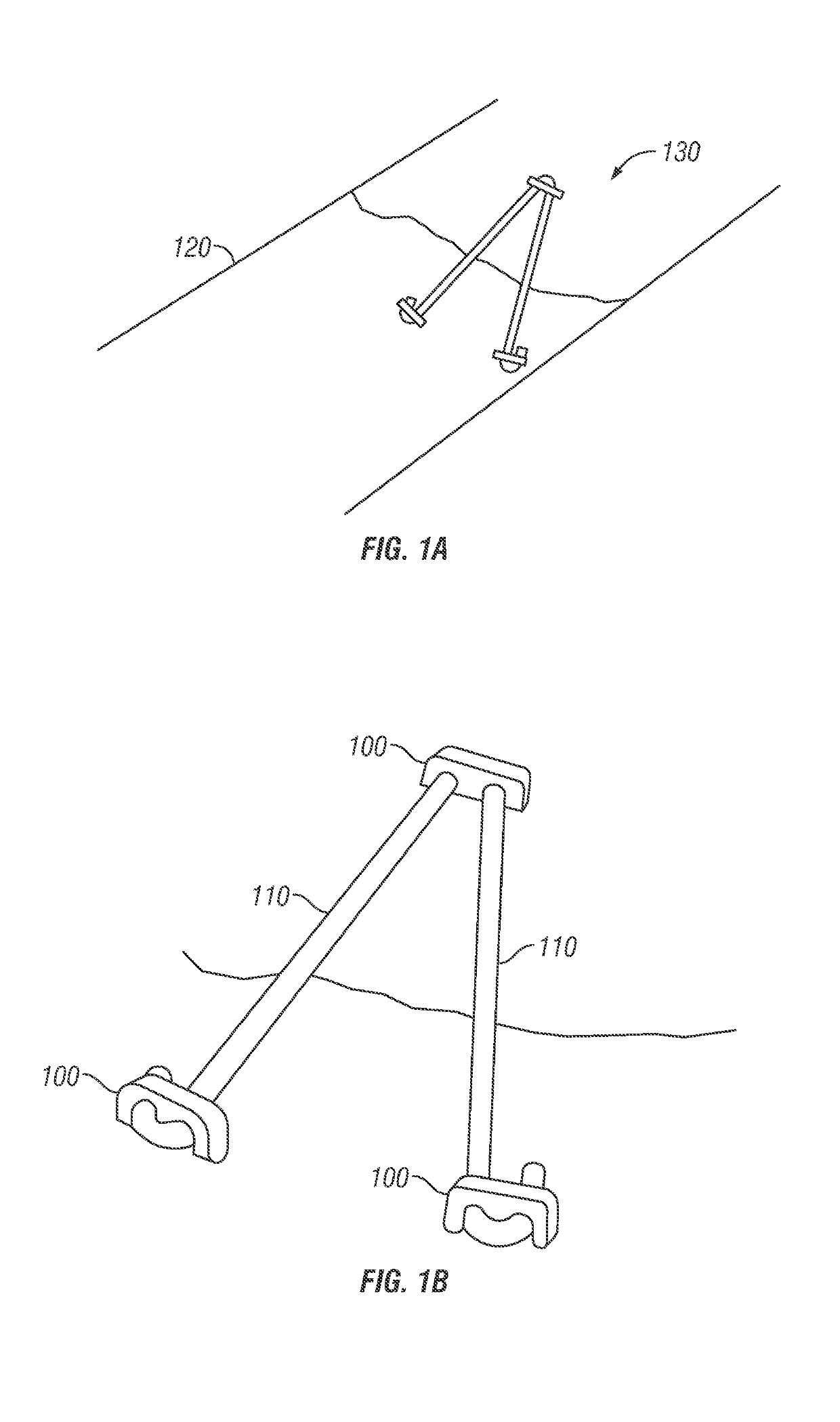
[0079]The vector compression system (130) of FIG. 1 illustrates a basic environment (e.g., at or over a fracture of a bone (120)) in which the present embodiments may be implemented. In the example shown, a fractured bone (120) is “sewn” together using a series of polymeric cored braided sutures (110) and anchors (100) placed on either side of the bone fracture site. The present disclosure presents several embodiments (e.g., 200, 300, 300, 400, 410) of novel designs for the anchors (100) that can be used in such a system. As noted above, the suture (110) can, for example, comprise the prior art cables disclosed in U.S. Pat. No. 6,589,246.

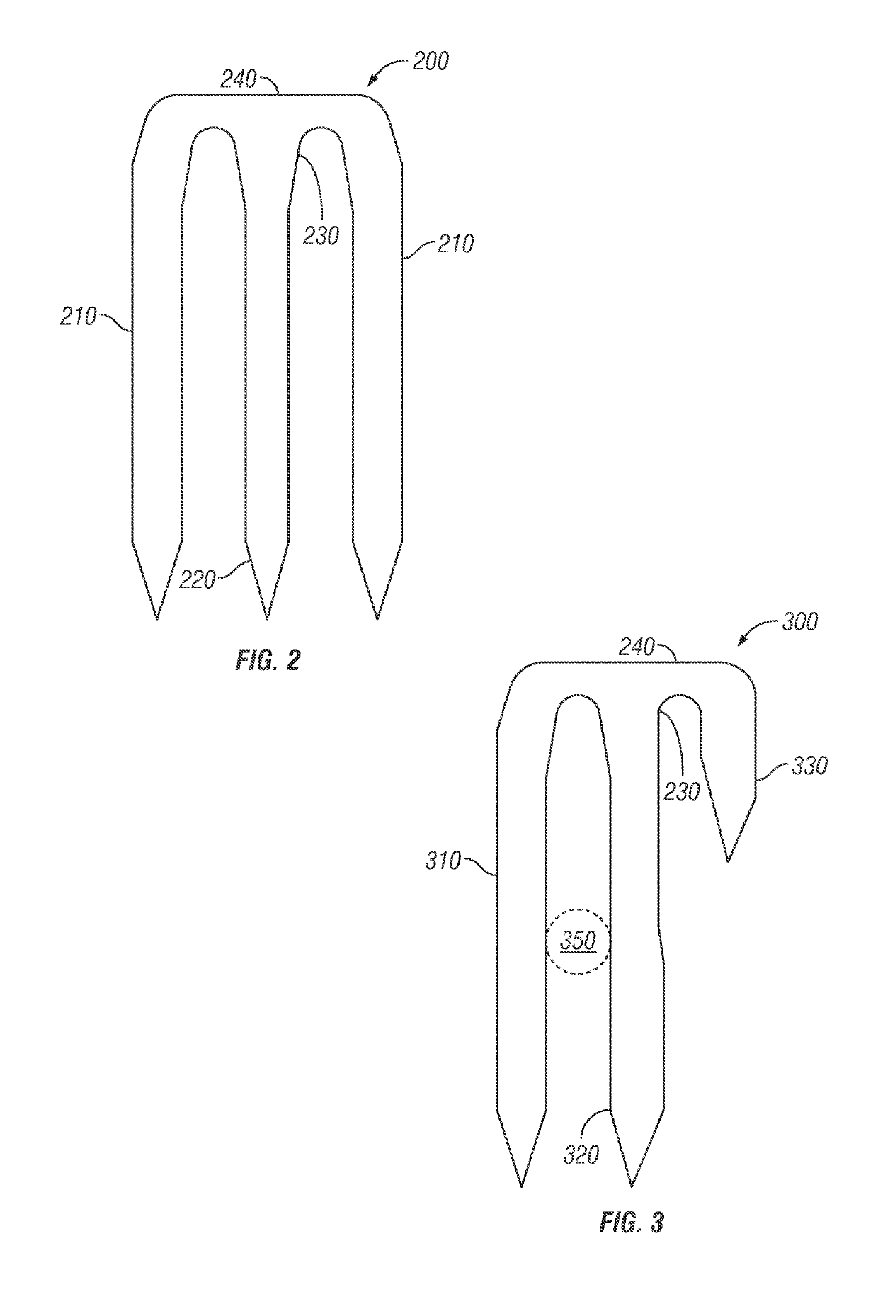
[0080]FIG. 2 shows the “E” shape of the first embodiment of basic anchor (200). In this embodiment, the anchor (200) includes two outside (210) prongs and one middle (220) prong with all three prongs having substantially equal lengths, and a bridge (240) extending between and coupled to (e.g., unitary with) the prongs. In contrast, the vector compre...


PUM


Abstract

This disclosure includes surgical anchors and related devices and methods that can be used for surgical bone fracture fixation. Some embodiments involve the use of a polymeric cored braided suture that can be held in place by anchors implanted or inserted into bone on each side of a fracture. In some embodiments, the present anchors can be secured into the bone while maintaining high tension (e.g., relative to certain prior art methods) in the suture during the deployment process. Some embodiments can provide for tensioning (e.g., using a polymeric cored braided suture) to compress the fracture and hold the bone in place, functioning as though the suture has sewn the bone (e.g., fragments or portions) together. This can, for example, provide rigid fixation of a fracture which may be important for healing to occur. The tension preload can provide compression to maintain fixation in the face of tensile and shear loads applied to the bone (e.g., as a result of movement and weight bearing).

Description

CROSS-REFERENCE OF RELATED APPLICATIONS[0001]This application is a national phase application under 35 U.S.C. § 371 of International Application No. PCT / US2014 / 025653 filed Mar. 13, 2014, which claims the benefit of priority to U.S. patent application Ser. No. 13 / 829,031, filed Mar. 14, 2013, the entire contents of each of which are incorporated by reference here in their entirety.BACKGROUND OF THE INVENTION[0002]A. Field of Invention[0003]The present invention involves devices and methods related to surgical bone fixation technology.[0004]B. Description of Related Art[0005]Bone is a remarkable material, and rare in its potential to heal completely following significant trauma. This potential is, at least in part, a product of the continuous remodeling that living bone undergoes and may only be fully realized under conditions conducive to healing. The goals of the treatment of fractures can include reduction of the fracture to as close to normal anatomy as possible and / or fracture f...

Claims


Application Information

Patent Timeline
Patent Type & Authority Patents(United States)
IPC IPC(8): A61B17/56A61B17/58A61B17/064A61B17/06A61B17/68A61F2/30A61B17/84A61B17/04A61B17/00
CPCA61B17/68A61B17/0401A61B17/0642A61B17/06166A61B17/06123A61B2017/0641A61B2017/0046A61B2017/00398A61B2017/0409A61B2017/0414A61B2017/0459A61B17/842
Inventor MATTCHEN, TERRY M.
Owner KINAMED
Why Eureka
Try Eureka