
System and method to measure capacitance of capacitive sensor array

a capacitive sensor and array technology, applied in measurement devices, instruments, surveying and navigation, etc., can solve the problems of increasing costs, less accurate position information, and low resolution, and achieve the effect of reducing the base capacitance of the array, facilitating more precise capacitance measurements, and reducing the cost of operation

Active Publication Date: 2019-08-20
CYPRESS SEMICON CORP
View PDF554 Cites 2 Cited by
  • Summary
  • Abstract
  • Description
  • Claims
  • Application Information

AI Technical Summary

Benefits of technology

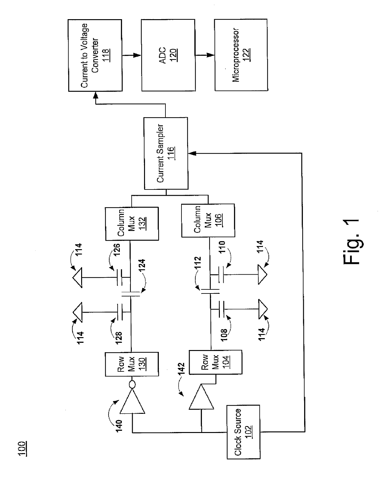
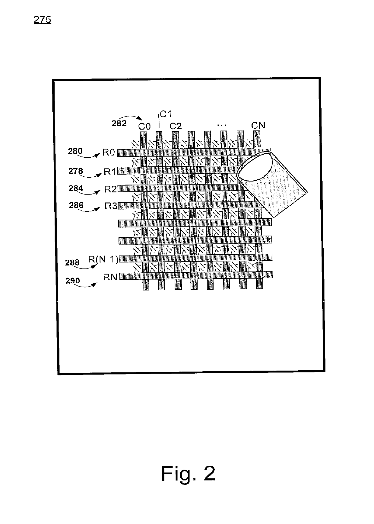
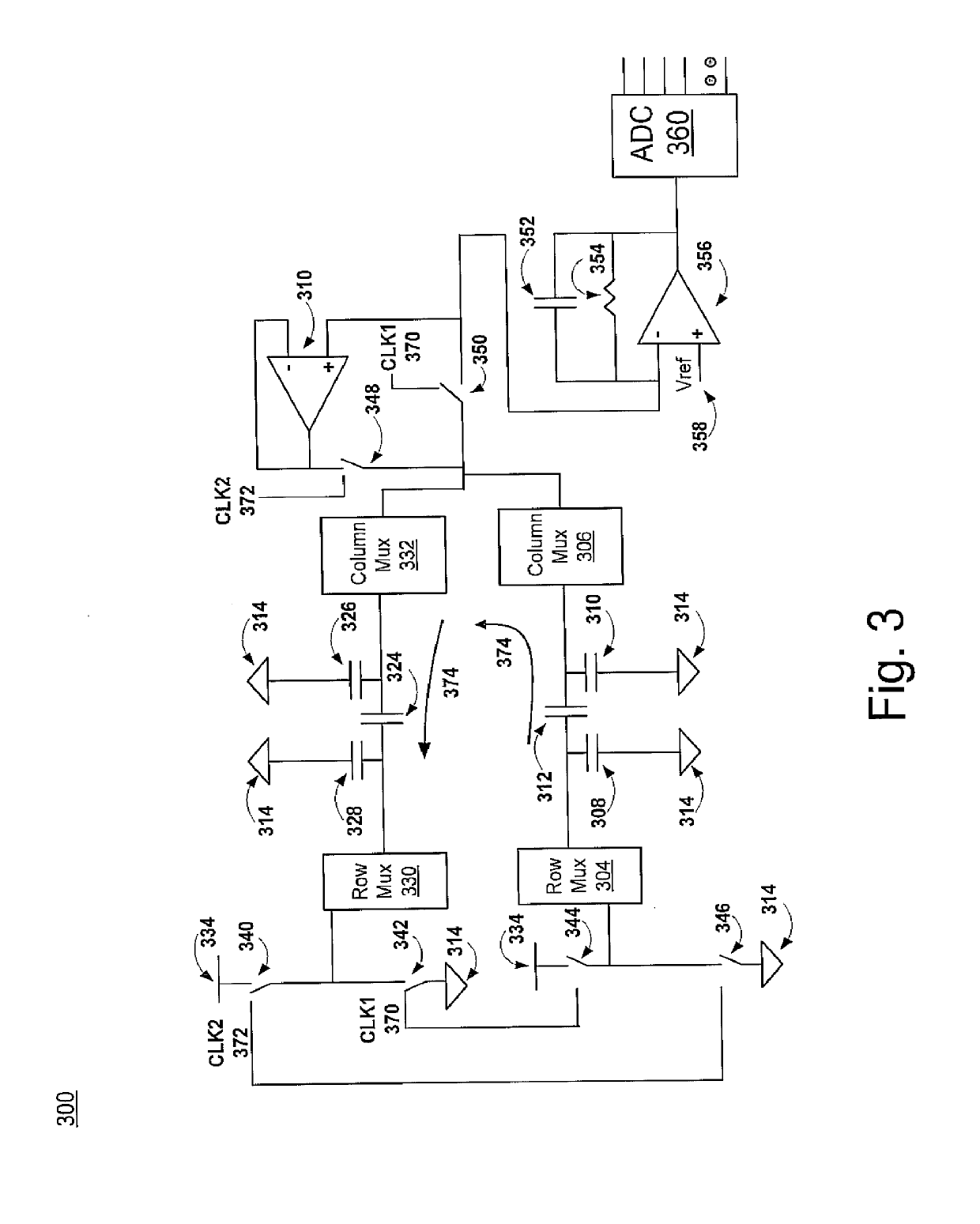
This patent is about a system and method for determining position information on a touch-sensitive array using differential capacitance measurements. This method allows for more precise detection of objects and requires fewer measurements, resulting in faster and more accurate scans. It also eliminates the need for current compensation circuitry and reduces the number of measurements for each column, making it easier to use. Overall, this patent improves the performance of capacitive sensor arrays.

Problems solved by technology

This leads to low resolution.
This current compensation solution requires extra hardware which increases costs and is slower as additional operations and settling times increase the time for each scan.
Thus, conventional capacitive sensor systems are susceptible to capacitive variations and utilize ground referenced capacitive measurements resulting in less accurate position information.

Method used


Image

  • System and method to measure capacitance of capacitive sensor array
  • System and method to measure capacitance of capacitive sensor array
  • System and method to measure capacitance of capacitive sensor array

Examples


example operations

[0055]With reference to FIG. 6, exemplary flowchart 600 illustrates example blocks used by various embodiments of the present invention. Although specific blocks are disclosed in flowchart 600, such blocks are examples. That is, embodiments are well suited to performing various other blocks or variations of the blocks recited in flowchart 600. It is appreciated that the blocks in flowchart 600 may be performed in an order different than presented, and that not all of the blocks in flowchart 600 may be performed. Flowchart 600 includes processes that, in various embodiments, are carried out by a processor under the control of computer-readable and computer-executable instructions. Embodiments of the present invention may thus be stored as computer readable media or computer-executable instructions including, but not limited to, a firmware update, software update package, or hardware (e.g., ROM).

[0056]In particular, FIG. 6 shows a flowchart of an exemplary process for determining posi...


PUM


Abstract

A system and method for determining position information. The method includes selecting a column, a first row, and a second row of a capacitive sensor array. The first row and second row intersect with the column of the capacitive sensor array. The method further includes measuring a differential capacitance between the first row and the second row and utilizing the differential capacitance in determining a location of an object proximate to the capacitive sensor array.

Description

RELATED U.S. APPLICATIONS[0001]This application is a continuation and claims the benefit of U.S. Utility application Ser. No. 12 / 239,692, filed Sep. 26, 2008, which issued as U.S. Pat. No. 8,321,174 on Nov. 12, 2012, which is hereby incorporated by reference.[0002]This application is related to commonly assigned, patent application Ser. No. 12 / 167,552, filed on Jul. 3, 2008, entitled “Method for Normalizing Signal From A High-Impedance Array of Capacitance Sensors,” which issued as U.S. Pat. No. 8,086,417 on Dec. 27, 2011, which is hereby incorporated by reference in its entirety.[0003]This application is related to commonly assigned, patent application Ser. No. 12 / 167,464, filed on Jul. 3, 2008, entitled “Method for Improving Scan Time And Sensitivity In Touch Sensitive User Interface Device,” which issued as U.S. Pat. No. 8,508,244 on Aug. 13, 2013, which is hereby incorporated by reference in its entirety.FIELD OF INVENTION[0004]Embodiments of the present invention generally rela...

Claims


Application Information

Patent Timeline
Patent Type & Authority Patents(United States)
IPC IPC(8): G01C9/00G06F3/044
CPCG06F3/044G06F3/0446G06F3/04166
Inventor MOYAL, NATHAN Y.OLSON, DANA JON
Owner CYPRESS SEMICON CORP
Learn More