

Surface mount dielectric antennas for wireless power transmitters
- Summary
- Abstract
- Description
- Claims
- Application Information
AI Technical Summary
Benefits of technology
Problems solved by technology
Method used
Image

Examples
Embodiment Construction
[0048]Numerous details are described herein in order to provide a thorough understanding of the example embodiments illustrated in the accompanying drawings. However, some embodiments may be practiced without many of the specific details, and the scope of the claims is only limited by those features and aspects specifically recited in the claims. Furthermore, well-known processes, components, and materials have not been described in exhaustive detail so as not to unnecessarily obscure pertinent aspects of the embodiments described herein.
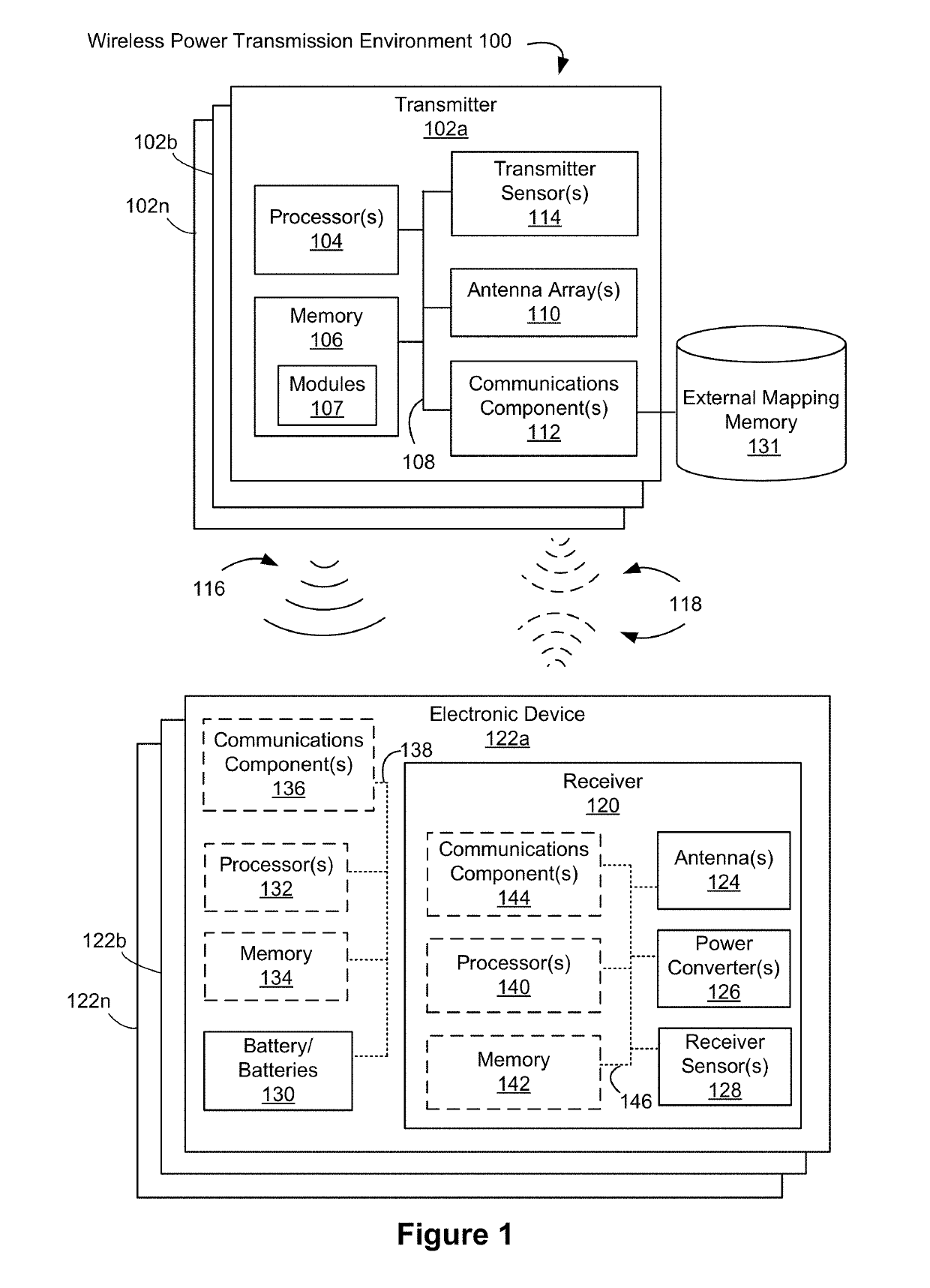
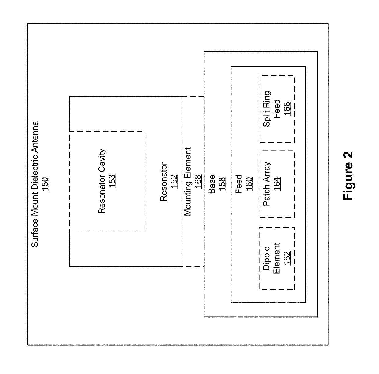
[0049]Various embodiments of surface mount dielectric antennas are described herein that addresses the shortcomings described above in conventional charging systems and with existing antenna designs. In some embodiments, a surface mount dielectric antenna described herein is a component of a transmitter and / or a receiver of a wireless power transmission environment 100 (e.g., as described with regard to FIG. 1). For example, a surface mount dielectr...
PUM
 Abstract
Description
Claims
Application Information