Heat sink for head up display

a technology for head-up displays and heat sinks, which is applied in the direction of cooling/ventilation/heating modifications, modifications by conduction heat transfer, semiconductor devices, etc., can solve the problems of limit the height of the heat sink fins, and achieve the effect of reducing the envelope of the heat sink, increasing heat dissipation, and maximizing heat dissipation

Active Publication Date: 2019-08-20
PANASONIC AUTOMOTIVE SYST OF AMERICA
View PDF11 Cites 0 Cited by
  • Summary
  • Abstract
  • Description
  • Claims
  • Application Information

AI Technical Summary

Benefits of technology

[0020]An advantage of the present invention is that it may provide increased heat dissipation when compared to traditional heat sinks both under natural convection conditions and under forced air conditions.
[0021]Another advantage of the present invention is that the heat sink may maximize heat dissipation, thus allowing the heat sink envelope to be reduced, and making the heat sink suitable for a head up display (HUD) application in which there are space constraints behind the instrument cluster where the HUD is installed. In contrast, a traditional heat sink has a larger envelope which is costlier due to including more material. Heat pipes used in conjunction with a large remote heat sink are also more expensive. The use of a copper heat sink, heat pipes, or a fan would be costlier and / or increase space requirements.

Problems solved by technology

The heat sink may possibly be applied to a head up display (HUD) in which there are severe space constraints behind the instrument cluster, and thus limitations on the heights of the heat sink fins.

Method used


Image

  • Heat sink for head up display
  • Heat sink for head up display
  • Heat sink for head up display

Examples


Embodiment Construction

[0027]The embodiments hereinafter disclosed are not intended to be exhaustive or limit the invention to the precise forms disclosed in the following description. Rather the embodiments are chosen and described so that others skilled in the art may utilize its teachings.

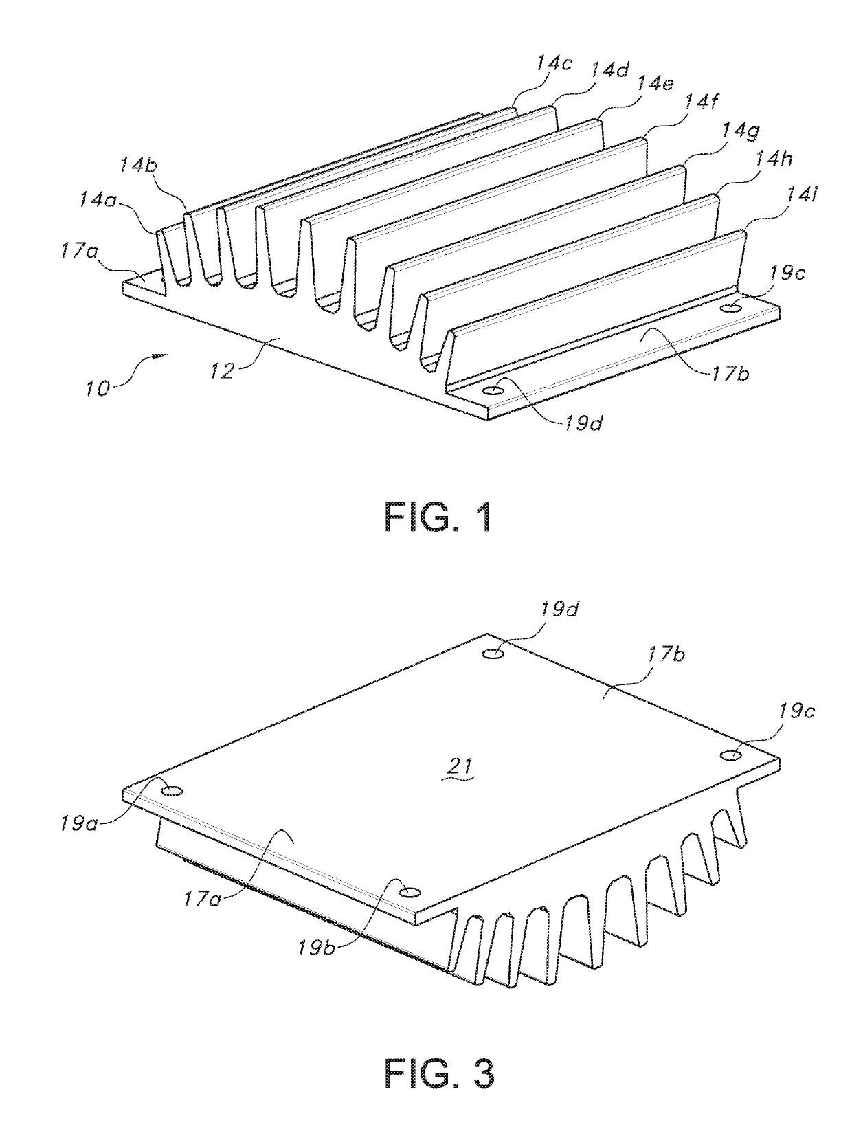
[0028]FIG. 1 is a perspective view of one embodiment of a heat sink 10 of the present invention, including a rectangular base 12 and nine rectangular fins 14a-i extending perpendicularly from base 12. Heat sink 10 may include two elongate flanges 17a-b on opposite sides thereof. Flanges 17a-b may include throughholes, such as throughholes 9a-d, through which heat sink 10 may be secured to a heat generating electronic component. As best shown in FIG. 3, a bottom surface 21 of heat sink 10 may be planar. Heat sink 10 may be formed of extruded aluminum, or some other material that is a good conductor of heat.

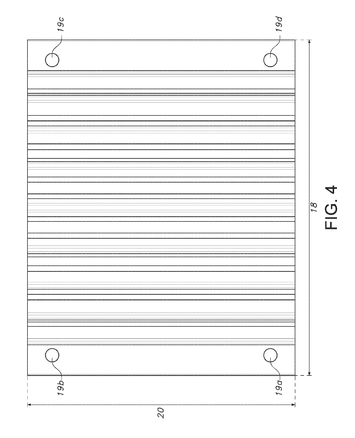
[0029]Base 12 may have a width 18 (FIG. 4) of approximately between 60 and 80 millimeters, and a length 20 of appr...


PUM


Abstract

A heat sink is for a heat source including an electronic component. The heat sink includes a base having a first surface and an opposite second surface. The first surface has a middle portion engaging the heat source. A plurality of elongate fins project from the second surface of the base and extend in directions perpendicular to the second surface. Middle ones of the fins are disposed opposite the middle portion of the first surface and have a greater height than other ones of the fins.

Description

CROSS-REFERENCED TO RELATED APPLICATIONS[0001]This application claims benefit of U.S. Provisional Application No. 62 / 393,228 filed on Sep. 12, 2016, which the disclosure of which is hereby incorporated by reference in its entirety for all purposes.BACKGROUND OF THE INVENTION1. Field of the Invention[0002]The present invention relates to a heat sink, and, more particularly, to a heat sink for dissipating heat from a head up display in a motor vehicle.2. Description of the Related Art[0003]Heat sinks are known to physically engage and carry heat away from electronic components that otherwise may be damaged by the heat. The heat sink typically is made of aluminum and has a base with a surface that contacts the electronic component. The heat sink also typically has a series of fins extending from the base in a direction away from the electronic component. The fins provide a large surface area within a limited three-dimensional space to thereby increase the rate of convection of heat fro...

Claims


Application Information

Patent Timeline
Patent Type & Authority Patents(United States)
IPC IPC(8): F28F7/00F28F13/00H05K7/20H01L23/367
CPCH01L23/367H05K7/2039
Inventor TANG-KONG, GERALD ANTHONY
Owner PANASONIC AUTOMOTIVE SYST OF AMERICA
Why Eureka
Try Eureka