Connecting rod and crosshead assembly for enhancing the performance of a reciprocating pump

a technology of connecting rods and crossheads, which is applied in the direction of positive displacement liquid engines, piston pumps, liquid fuel engines, etc., can solve the problems of critical downtime of reciprocating pumps, short and frequent duty cycles of reciprocating pumps, and the performance, reliability, and/or load bearing capacity of mechanical linkages, etc., to achieve the effect of reducing axial displacemen

Active Publication Date: 2019-08-27
SPM OIL & GAS INC
View PDF10 Cites 25 Cited by
  • Summary
  • Abstract
  • Description
  • Claims
  • Application Information

AI Technical Summary

Benefits of technology

[0007]In yet another exemplary embodiment, the apparatus further includes a clamp, the clamp including a pair of plates adapted to engage both the main body of the crosshead and the respective opposing end portions of the small end, and a tensioner connected to the plates and adapted to apply tension therebetween; wherein, when the tensioner applies tension between the plates, the clamp is adapted to prevent, or at least reduce, axial displacement of the small end within the bearing and relative to the crosshead.
[0066]In an exemplary embodiment, the reciprocating pump assembly further includes a clamp, the clamp including: a pair of plates engaging both the main body of the crosshead and the respective opposing end portions of the small end, and a tensioner connected to, and applying tension between, the plates to prevent, or at least reduce, axial displacement of the small end relative to the crosshead.

Problems solved by technology

During such operations, these reciprocating pumps are often subject to short and frequent duty cycles, and are required to deliver a fluid or slurry to the wellbore at pressures up to 20,000 psi.
The performance, reliability, and / or load bearing capacity of the mechanical linkages, i.e., the connecting rods and the crossheads, is often an issue in the field due to the extreme duty cycles of reciprocating pumps employed in oilfield operations.
Failure of these components may cause critical downtime of the reciprocating pump during oilfield operations and / or inflict damage to well tools or other components on the well site.

Method used


Image

  • Connecting rod and crosshead assembly for enhancing the performance of a reciprocating pump
  • Connecting rod and crosshead assembly for enhancing the performance of a reciprocating pump
  • Connecting rod and crosshead assembly for enhancing the performance of a reciprocating pump

Examples


Embodiment Construction

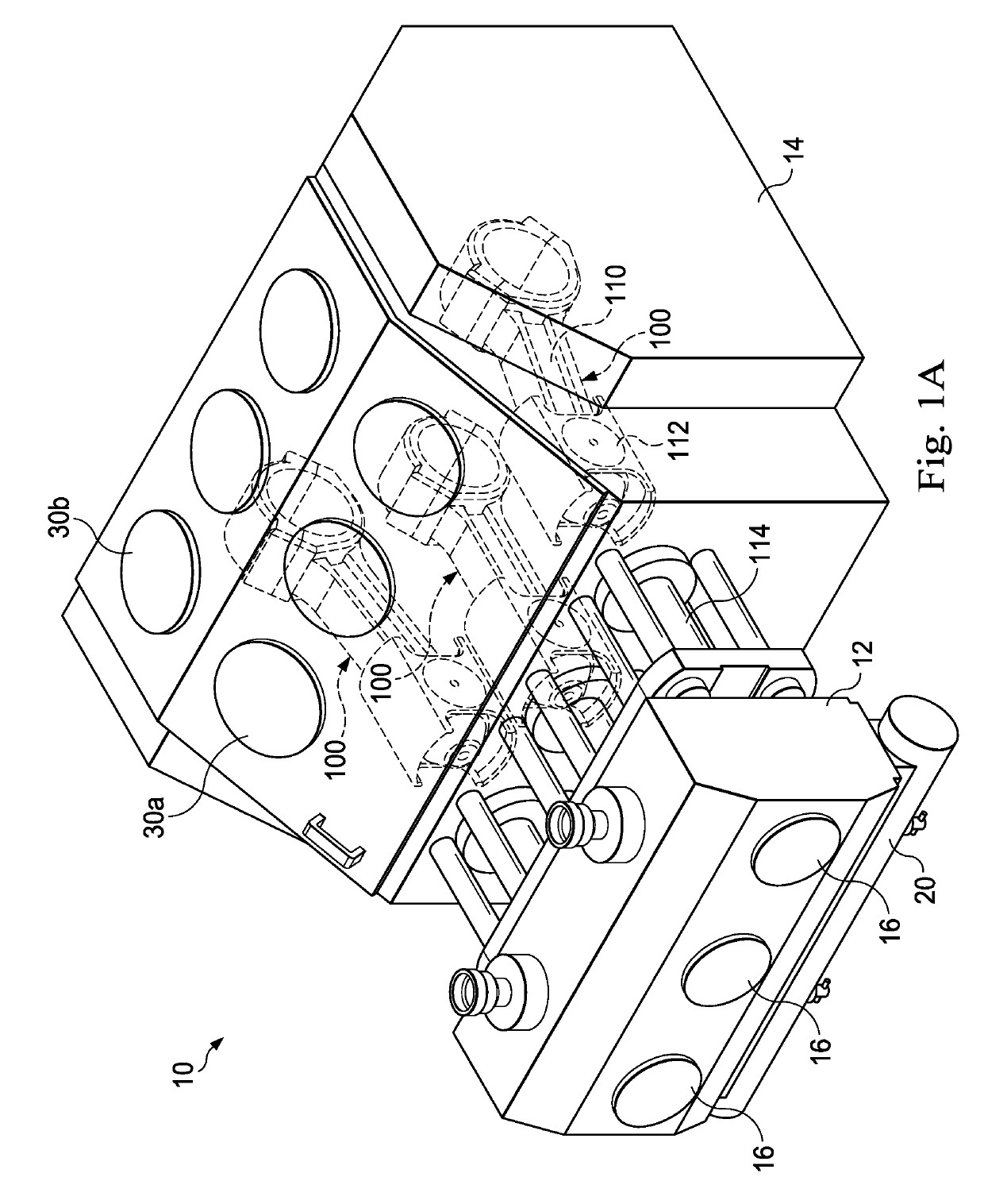
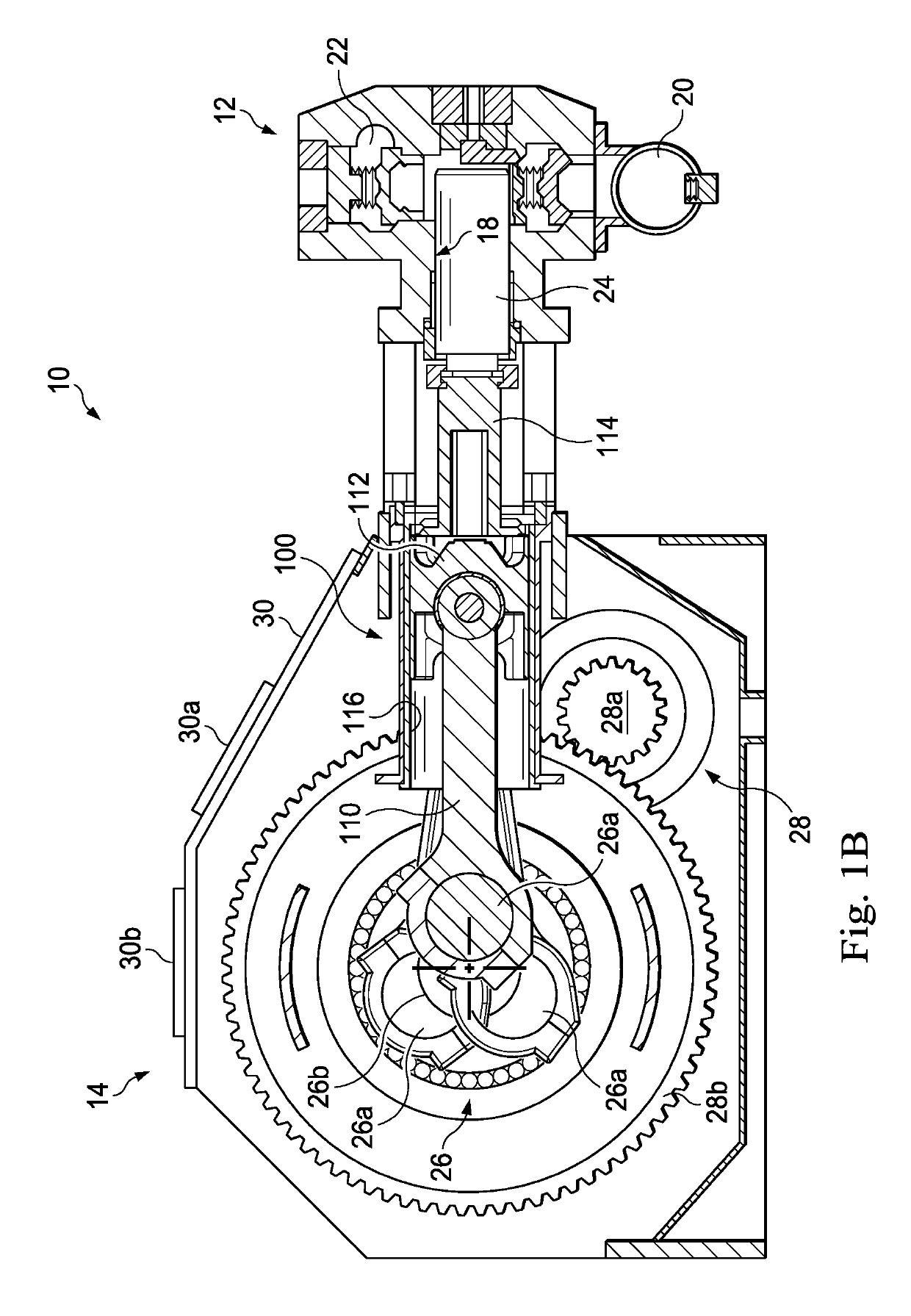
[0082]In an exemplary embodiment, as illustrated in FIGS. 1A and 1B, a reciprocating pump assembly is schematically illustrated and generally designated by the reference numeral 10. The reciprocating pump assembly 10 includes a fluid end 12 and a power end 14. In several exemplary embodiments, the reciprocating pump assembly 10 is a triplex with the fluid end 12 having a set of three cylinders 16, each including a plunger bore 18. Although the reciprocating pump assembly 10 is depicted in FIG. 1 as a triplex, the reciprocating pump assembly 10 may include any number of cylinders 16 such as, for example, one cylinder, two cylinders (duplex), four cylinders (quadriplex), five cylinders (quintuplex), or more. The cylinders 16 and their respective plunger bores 18 are arranged transversely across the fluid end 12. The plunger bores 18 are each in fluid communication with a suction manifold 20 and a discharge manifold 22. The fluid end 12 further includes plungers 24 that are received by...


PUM


Abstract

A method and apparatus for a reciprocating pump assembly, including a crosshead and a connecting rod. The crosshead includes a main body having a cylindrical bore formed therethrough and defining a bearing surface, and a window formed through the main body and into the cylindrical bore. The connecting rod includes a small end disposed within the cylindrical bore and a beam portion extending through the window and being connected to the small end. In an exemplary embodiment, a bearing including a tubular body and a cutout is disposed within the cylindrical bore. In another exemplary embodiment, a clamp engages both the main body of the crosshead and the respective opposing end portions of the small end, thus reducing axial displacement of the small end relative to the crosshead.

Description

CROSS-REFERENCE TO RELATED APPLICATION[0001]This application claims the benefit of the filing date of, and priority to, U.S. Application No. 62 / 181,463, filed Jun. 18, 2015, the entire disclosure of which is hereby incorporated herein by reference.TECHNICAL FIELD[0002]The present disclosure relates generally to a reciprocating pump and, more specifically, to enhancing the performance, reliability, and / or capacity of the reciprocating pump by equipping the reciprocating pump with an improved connecting rod and crosshead assembly according to the present disclosure.BACKGROUND OF THE DISCLOSURE[0003]Reciprocating pumps are used in connection with various oilfield operations such as, for example, cementing, acidizing, or fracturing of a subterranean wellbore. During such operations, these reciprocating pumps are often subject to short and frequent duty cycles, and are required to deliver a fluid or slurry to the wellbore at pressures up to 20,000 psi. An exemplary reciprocating pump for...

Claims


Application Information

Patent Timeline
Patent Type & Authority Patents(United States)
IPC IPC(8): F04B53/14F16C5/00F04B9/04F04B53/22F04B53/00F04B53/16F04B1/02
CPCF04B1/02F04B9/045F04B53/22F04B53/147F04B53/006F04B53/16F16C5/00
Inventor WAGNER, BRYAN
Owner SPM OIL & GAS INC
Why Eureka
Try Eureka