
Calibration of monolithic crystal-based detectors

a monolithic crystal and detector technology, applied in the field of self-calibration of monolithic crystal-based detectors for emission tomography, can solve the problems of limited practical use of monolithic crystals in commercial systems, complex and time-consuming process for training data acquisition, and poor performance of monolithic crystal-based detectors, etc., to achieve simple and efficient calibration

Active Publication Date: 2019-08-27
MOLECUBES
View PDF3 Cites 4 Cited by
  • Summary
  • Abstract
  • Description
  • Claims
  • Application Information

AI Technical Summary

Benefits of technology

[0007]It is an object of embodiments of the present invention to provide simple and efficient calibration for monolithic crystal detectors.
[0008]It is an advantage of embodiments of the present invention that a cheap and simple calibration method is provided. It is a further advantage of embodiments of the present invention that a calibration is provided which may be performed in the field, e.g. on a detector which is assembled in a gantry of an imaging system.
[0009]It is an advantage of embodiments of the present invention that a calibration can be performed which uses only training data that is easily obtainable, e.g. comparable to other measurements typically performed for quality assurance on regular basis.

Problems solved by technology

However, monolithic crystal-based detectors are known to perform poorly if a conventional, simple method known in the art is used for obtaining spatial information of interaction events.
However, the acquisition of training data may be a complex and time-consuming process, may happen off-line and may require an accurate robotic stage.
These drawbacks entail the main limitation for practical use of monolithic crystals in commercial systems.
In order to achieve a good detector performance, monolithic detectors may require costly and complex calibration procedures, which may have slowed the introduction of monolithic crystal-based detectors in current commercial systems.
The calibration procedures known in the art often require training data, and thus require a long and complex procedure for obtaining these training data.
For example, such methods may require data acquisition over many hours or even days in order to calibrate one detector.
If several detectors need to be calibrated in parallel, this entire setup has to be replicated as many times. In addition, calibration procedures known in the art cannot be performed on detectors which are already assembled in the gantry of the imaging scanner, since this may not allow a proper follow-up of the calibration status.
However, the training process may still require individual detector calibration for non-assembled detectors, which does not allow for detector recalibration once the detectors are assembled in the system and the system is operational in the field.
This also constitutes an important drawback in modern systems that use avalanche photo diode (APD) detectors or silicon photomultiplier (SiPM) photosensors for the readout of the scintillation crystals.
However, various factors which are difficult to predict in an analytical approach may influence the behaviour of a detector significantly, such as assembling differences, photosensor gain variations, electronic noise, or couplings.

Method used


Image

  • Calibration of monolithic crystal-based detectors
  • Calibration of monolithic crystal-based detectors
  • Calibration of monolithic crystal-based detectors

Examples


Embodiment Construction

[0067]The present invention will be described with respect to particular embodiments and with reference to certain drawings but the invention is not limited thereto but only by the claims. The drawings described are only schematic and are non-limiting. In the drawings, the size of some of the elements may be exaggerated and not drawn on scale for illustrative purposes. The dimensions and the relative dimensions do not correspond to actual reductions to practice of the invention.

[0068]Furthermore, the terms first, second and the like in the description and in the claims, are used for distinguishing between similar elements and not necessarily for describing a sequence, either temporally, spatially, in ranking or in any other manner. It is to be understood that the terms so used are interchangeable under appropriate circumstances and that the embodiments of the invention described herein are capable of operation in other sequences than described or illustrated herein.

[0069]Moreover, t...


PUM


Abstract

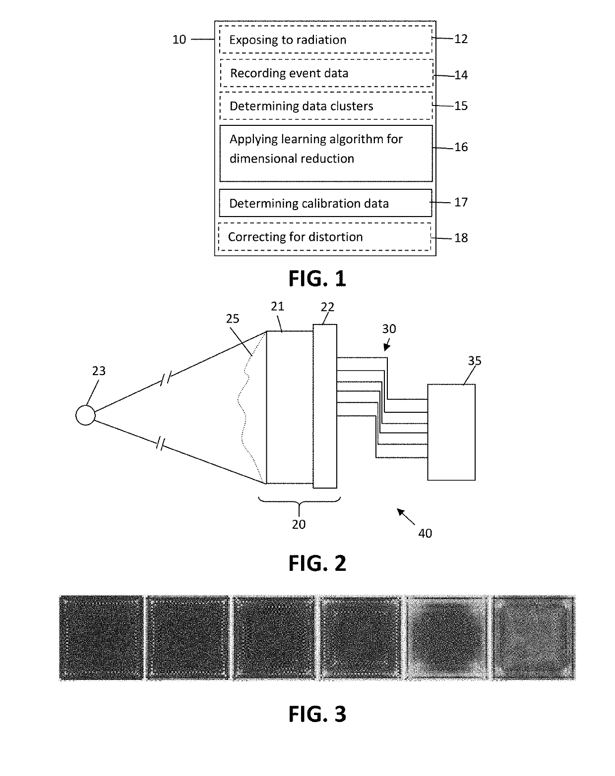
A calibration method for calibrating at least one gamma radiation detector includes a monolithic scintillation crystal. The calibration method comprises obtaining event data for a plurality of scintillation events. The event data for each scintillation event includes a plurality of location sensitive signals observed by the at least one gamma radiation detector to be calibrated, applying an unsupervised learning algorithm to embed the event data on a low-dimensional manifold, and obtaining calibration data considering the low-dimensional manifold embedding.

Description

FIELD OF THE INVENTION[0001]The invention relates to the field of detectors for emission tomography. More specifically, it relates to a method and device for performing a self-calibration of a monolithic crystal-based detector for emission tomography.BACKGROUND OF THE INVENTION[0002]Detectors based on monolithic scintillation crystals, for example monolithic scintillation detectors for Positron Emission Tomography (PET) or Single Photon Emission Computed Tomography (SPECT) imaging, have many advantages over pixelated detectors. Replacing pixelated detectors by monolithic scintillation crystal detectors may reduce the cost per unit volume and may increase the sensitivity and the spatial, energy and timing resolution of the detector. In addition, on thick monolithic crystal-based detectors, the depth-of-interaction (DOI) may be determined without additional hardware. However, monolithic crystal-based detectors are known to perform poorly if a conventional, simple method known in the a...

Claims


Application Information

Patent Timeline
Patent Type & Authority Patents(United States)
IPC IPC(8): G01T7/00G06K9/00G06K9/36G01T1/164
CPCG01T1/1648G06V10/247G06F2218/00G01T7/005
Inventor ESPANA PALOMARES, SAMUEL
Owner MOLECUBES
Learn More