Optical system and method for transmitting a source image

a source image and optical system technology, applied in the field of optical systems and methods for transmitting source images, can solve the problems of restricted field of view and restricted field of view of such optical systems

Active Publication Date: 2019-08-27
CARL ZEISS SMT GMBH
View PDF23 Cites 14 Cited by
  • Summary
  • Abstract
  • Description
  • Claims
  • Application Information

AI Technical Summary

Benefits of technology

[0031]Preferably, in the case of the measure mentioned above, the wavelength spectrum is subdivided into three wavelength ranges, preferably into red, green and blue. The division of the total spectral range of the light emanating from the source image can be achieved via spectral filters, for example.
[0032]In a preferred development of the measure mentioned above, the optical waveguide arrangement has a first optical waveguide for the propagation of light in the first wavelength range and has at least one separate second optical waveguide for the propagation of light in the at least one second wavelength range.
[0033]In accordance with this configuration, therefore, separate transmission channels are used for the transmission of the different wavelength ranges. In this case, the individual optical waveguides are preferably arranged or stacked one above another transversely with respect to the light propagation direction in the optical waveguides.
[0034]In a further preferred configuration, the optical waveguide arrangement has a first optical waveguide, into which the first input coupling element couples the light from the first subfield, and at least one second optical waveguide, into which the at least one second input coupling element couples the light from the at least one second subfield.
[0035]In this configuration, also for the transmission of the individual subfields of the source image in each case a dedicated transmission channel is used, which can be arranged in a manner lying one above another.
[0036]In connection with the abovementioned measure of the spectral division of the source image light into three color channels and in the case where the source image is spatially divided into two subfields, this results overall in 2×3, i.e. six, transmission channels for the source image, corresponding to the division of the source image into two subfields and the division of the wavelength spectrum into three wavelength ranges.

Problems solved by technology

In general, in the case of optical systems having the construction described above, it has been found that the field of view of such an optical system is restricted, that is to say that the entire source image or, in other words, the entire field angle spectrum of the light emanating from the source image cannot be transmitted by the optical system.
In general, the field of view is restricted, however, even during monochromatic transmission.

Method used


Image

  • Optical system and method for transmitting a source image
  • Optical system and method for transmitting a source image
  • Optical system and method for transmitting a source image

Examples


Embodiment Construction

[0107]In order to afford a better understanding of the configurations according to the disclosure of optical systems for transmitting a source image, which configurations will be described later, firstly the physical relationships of diffractive input coupling of light into an optical waveguide, the propagation of the light in the optical waveguide and the diffractive output coupling of the light from the optical waveguide will be explained with reference to FIGS. 1 to 8.

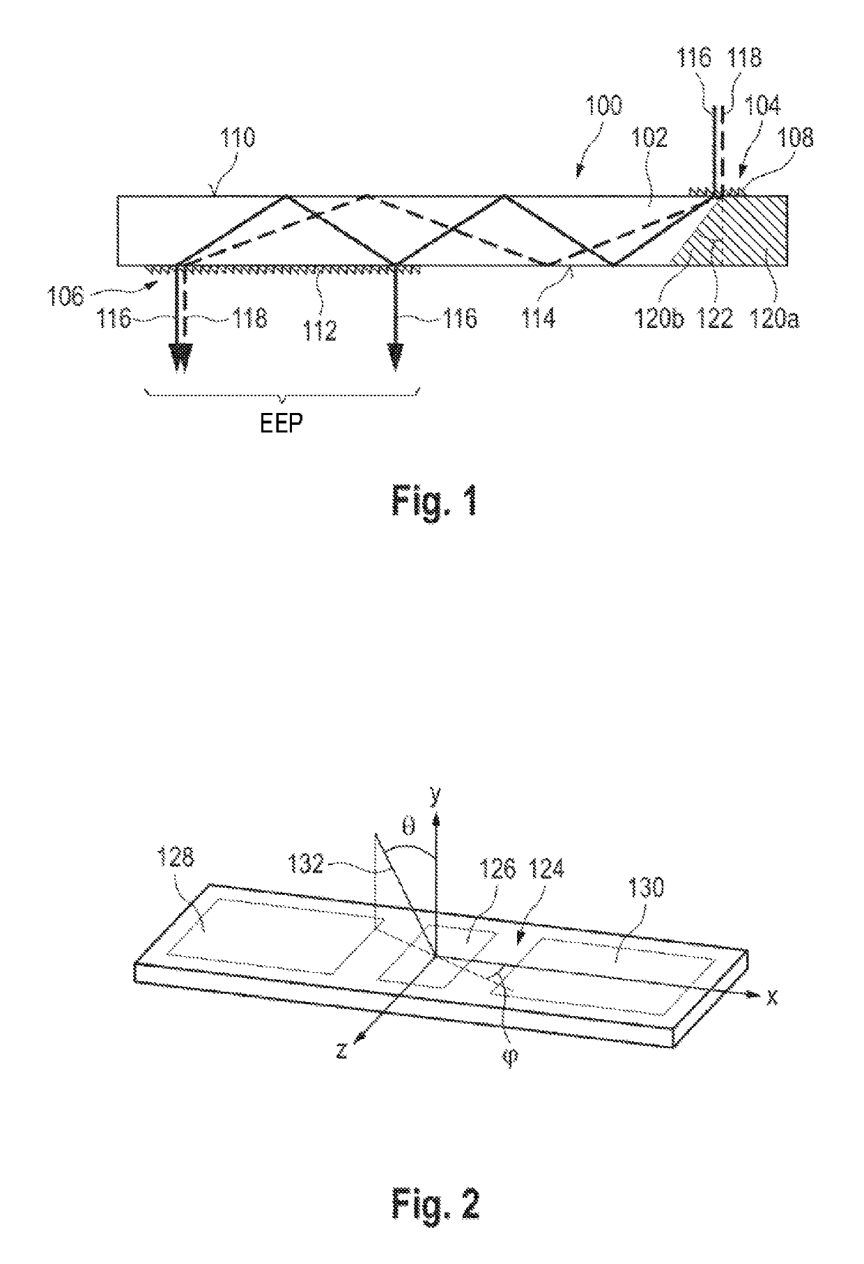
[0108]FIG. 1 firstly shows an optical waveguide arrangement 100 including an optical waveguide 102, which is configured as a plane-parallel plate. A diffractive input coupling arrangement 104 and a diffractive output coupling arrangement 106 are arranged at the optical waveguide arrangement 100.

[0109]The diffractive input coupling arrangement 104 has a transmissive diffraction grating structure 108, which is configured for example as a blazed grating and which is arranged at a first surface 110 of the optical wavegu...


PUM


Abstract

An optical system for transmitting a source image is provided. Light having a field angle spectrum emanates from the source image. The optical system includes an optical waveguide arrangement, in which light can propagate by total internal reflection. The optical system also includes a diffractive optical input coupling arrangement for coupling the light emanating from the source image into the optical waveguide arrangement. The optical system further includes a diffractive optical output coupling arrangement for coupling the light that has propagated in the optical waveguide arrangement out from the optical waveguide arrangement. The disclosure also provides related methods.

Description

CROSS-REFERENCE TO RELATED APPLICATIONS[0001]The present application is a continuation of, and claims benefit under 35 USC 120 to, U.S. application Ser. No. 16 / 008,394, filed Jun. 14, 2018, now U.S. Pat. No. 10,191,288, which is a continuation of, and claims benefit under 35 USC 120 to, international application PCT / EP2016 / 080902, filed Dec. 14, 2016, which claims benefit under 35 USC 119 of German Application No. 10 2015 122 055.5, filed Dec. 17, 2015. The entire disclosure of these applications are incorporated by reference herein.FIELD[0002]The disclosure relates to an optical system and method for transmitting a source image.BACKGROUND[0003]An optical system and a method for transmitting a source image are disclosed in the article by Tapani Levola: “Diffractive optics for virtual reality displays”, Journal of the SID 14 / 5, 2006, pages 467 to 475. Further optical systems and methods for transmitting a source image are known from US 2014 / 0140653 A1, U.S. Pat. No. 8,233,204 B1, US ...

Claims


Application Information

Patent Timeline
Patent Type & Authority Patents(United States)
IPC IPC(8): G02B6/26G02B27/01F21V8/00G02B5/18
CPCG02B5/1819G02B27/0172G02B2027/011G02B2027/0112G02B2027/0116G02B2027/0125G02B2027/0178G02B6/0026G02B6/005G02B6/0076
Inventor SINGER, WOLFGANGKLEEMANN, BERNDDEGEN, ARTUR
Owner CARL ZEISS SMT GMBH
Why Eureka
Try Eureka