Diffractive optical element, objective optical system including the same, and optical pickup including the same

a technology optical pickups, applied in the field an objective optical system including the same and an optical pickup, can solve the disadvantageous lowering of the design freedom of diffractive optical elements, and achieve the effect of low wavelength dependence and high degree of design freedom

Active Publication Date: 2010-09-21
PANASONIC CORP
View PDF11 Cites 4 Cited by
  • Summary
  • Abstract
  • Description
  • Claims
  • Application Information

AI Technical Summary

Benefits of technology

[0006]The present invention was devised in consideration of this disadvantage and an object of the invention is providing a diffractive optical element having diffraction efficiency with low wavelength dependency and a high degree of design freedom.
[0010]According to the present invention, a diffractive optical element having diffraction efficiency with low wavelength dependency and a high degree of design freedom can be realized.

Problems solved by technology

In the technique disclosed in Patent Document 1, however, since it is necessary to satisfy the conditional formula (*), materials usable for the optical parts are limited, and hence, the degree of design freedom of the diffractive optical element is disadvantageously lowered.

Method used


Image

  • Diffractive optical element, objective optical system including the same, and optical pickup including the same
  • Diffractive optical element, objective optical system including the same, and optical pickup including the same
  • Diffractive optical element, objective optical system including the same, and optical pickup including the same

Examples


embodiment 1

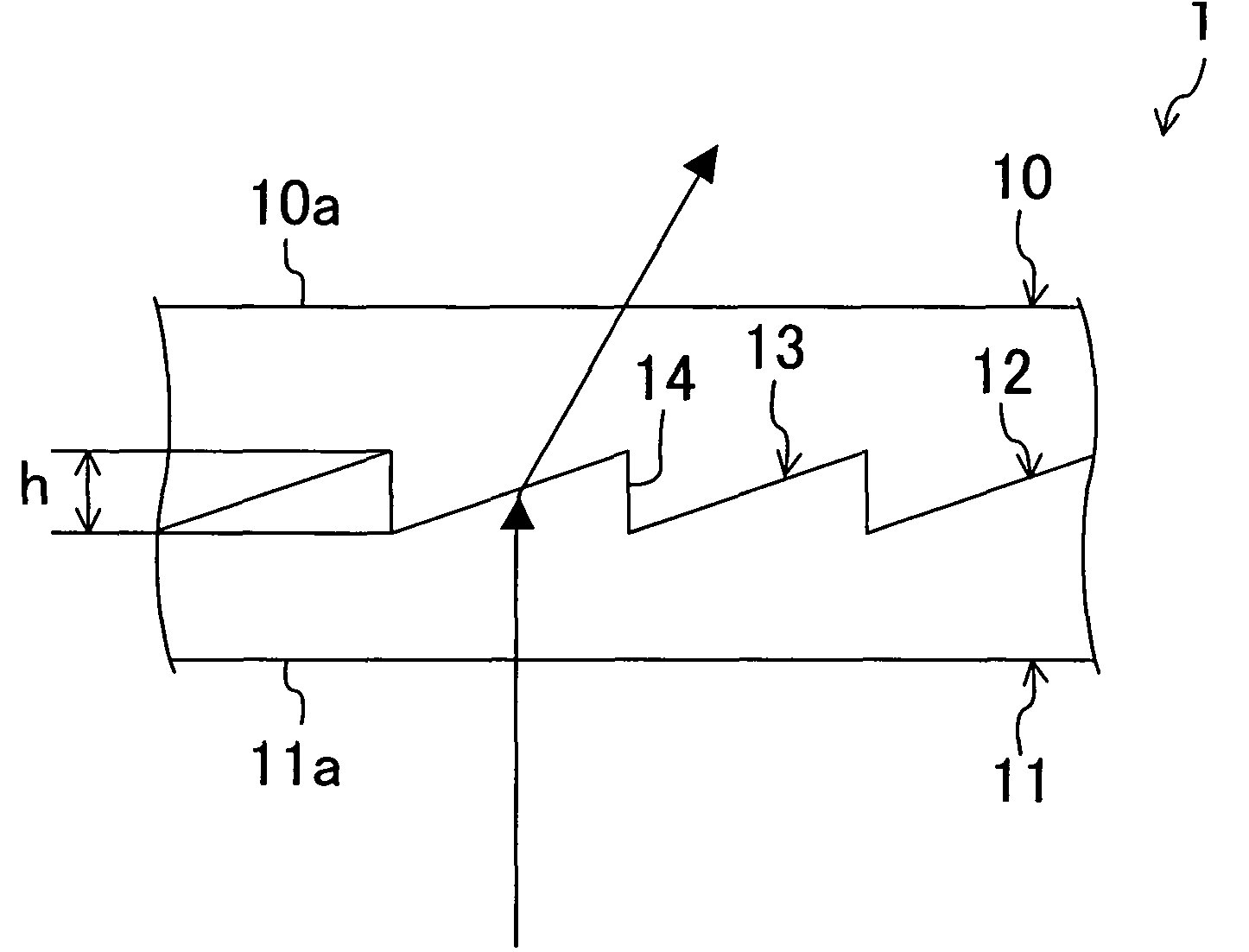
[0047]FIG. 1 is a schematic cross-sectional view of a diffractive optical element 1 according to Embodiment 1.

[0048]The diffractive optical element 1 of this embodiment diffracts a plurality of kinds of laser beams of different wavelengths (preferably of mutually discrete wavelengths). The diffractive optical element 1 includes a first optical part 10 and a second optical part 11 respectively made of optically transparent glass, resin or the like. The first optical part 10 and the second optical part 11 are bonded to each other, and a bonded surface 12 therebetween is configured as a diffraction surface 13 formed of a plurality of regularly arranged structural units, each being a concave and / or a convex (specifically, a diffraction surface having a saw-tooth-shaped cross-section in which a plurality of fine convexes 14 each having a substantially triangular cross-section (whose top may be chamfered or R-chamfered or whose sides may be curved) are regularly arranged). On the other ha...

embodiment 2

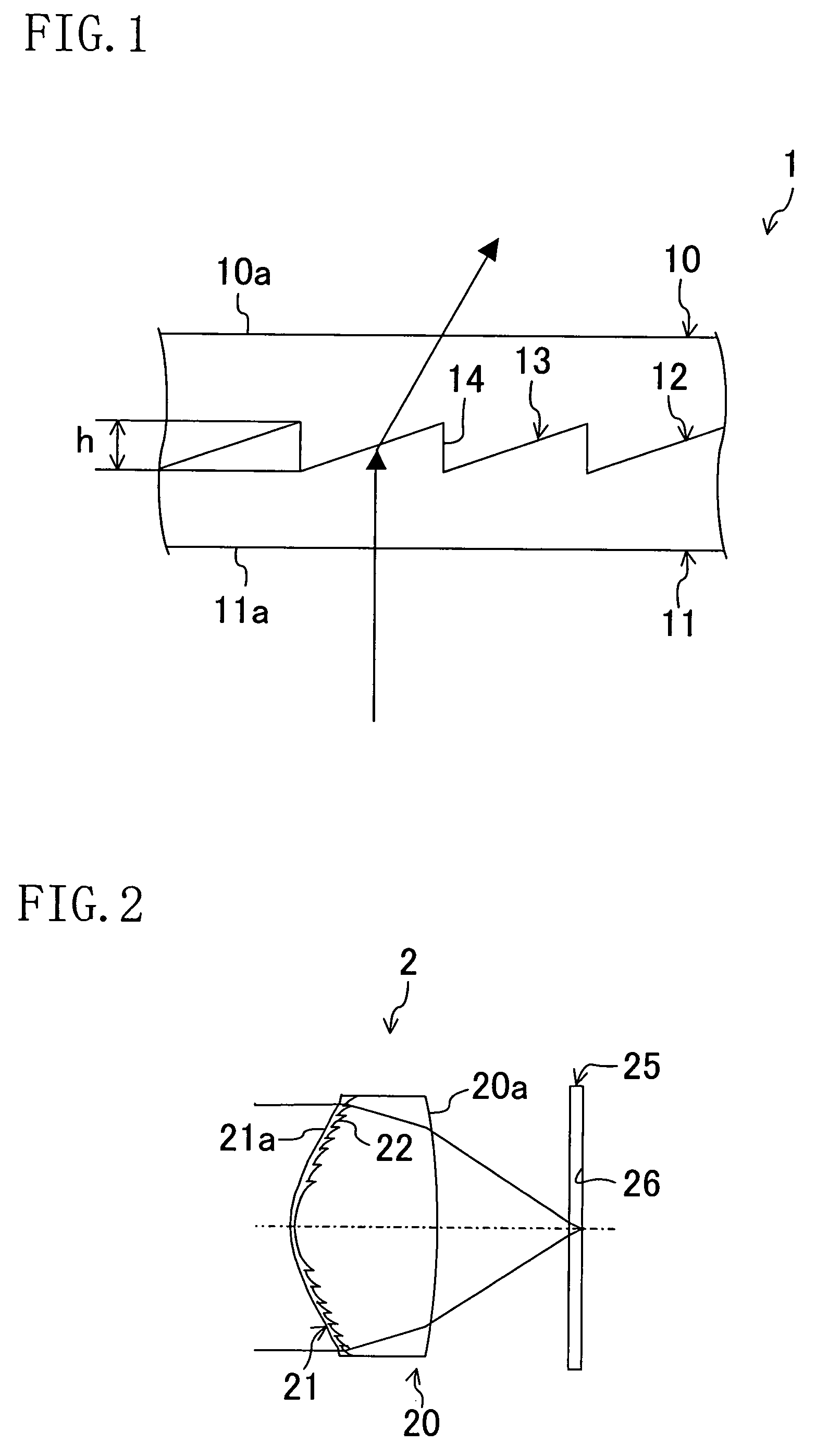
[0065]In Embodiment 1, one embodiment of the diffractive optical element of the present invention is described by exemplifying the diffractive optical element 1 of the so-called parallel plate type usable as a phase correcting element or the like. The diffractive optical element of this invention is, however, not limited to the embodiment described in Embodiment 1 but may be an optical element in the form of, for example, a lens or a prism. In Embodiment 2, an example of the diffractive optical element in the form of a lens will be described. Specifically, an objective lens used for respectively focusing a plurality of kinds of laser beams on information recording surfaces 26 of optical information recording media 25 like optical discs such as a CD (compact disc), a DVD (digital versatile disc) and a BD (blu-ray disc (registered trademark)) will be exemplified in this embodiment.

[0066]FIG. 2 is a schematic cross-sectional view of a diffractive optical element 2 according to Embodime...

embodiment 3

[0081]In Embodiment 3, an example of an optical pickup using the diffractive optical element 1 described in Embodiment 1 as a phase correcting element will be described. In the description of Embodiment 3, FIG. 1 is referred to in the same manner as in Embodiment 1. Also, same reference numerals are used to refer to elements having substantially the same functions as in Embodiment 1 so as to omit the description.

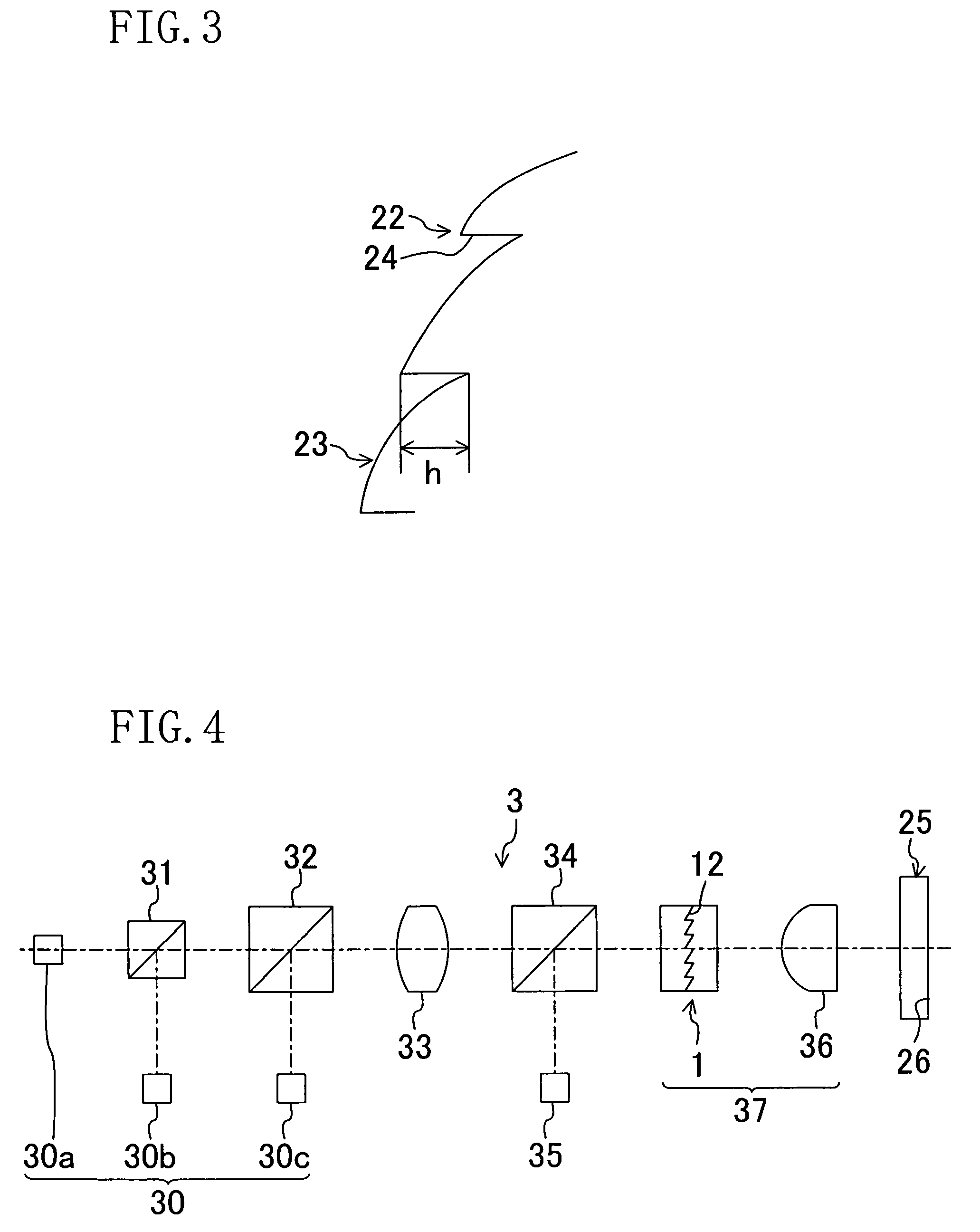
[0082]FIG. 4 is a diagram for showing the architecture of a principal part of an optical pickup 3 according to Embodiment 3.

[0083]The optical pickup 3 includes a multiple wavelength light source 30, beam splitters 31 and 32, a collimator 33, a beam splitter 34, a detector 35 and an objective optical system 37.

[0084]The multiple wavelength light source 30 can selectively emit plurality of kinds of laser beams of different wavelengths. Specifically, the multiple wavelength light source 30 emits a laser beam (out of the plural kinds of laser beams) according to the type of opti...


PUM

PropertyMeasurementUnit
thicknessaaaaaaaaaa
thicknessaaaaaaaaaa
thicknessaaaaaaaaaa

Abstract

A diffractive optical element includes a first optical part and a second optical part bonded to each other with a bonded surface therebetween configured as a diffraction surface. In this diffractive optical element, the diffraction order of diffracted light with the largest quantity of light out of diffracted light for one of a plurality of kinds of laser beams obtained on the diffraction surface is different from the diffraction order for at least another laser beam.

Description

CROSS-REFERENCE TO RELATED APPLICATIONS[0001]This application claims priority under 35 U.S.C. §119 on Patent Application No. 2006-127367 filed in Japan on May 1, 2006, the entire contents of which are hereby incorporated by reference.[0002]Also, this application claims the benefit of U.S. Provisional Application No. 60 / 878,675 filed on Jan. 5, 2007.BACKGROUND OF THE INVENTION[0003]The present invention relates to a diffractive optical element, an objective optical system including the same and an optical pickup including the same.[0004]According to, for example, Patent Document 1 (Japanese Laid-Open Patent Publication No. 9-127321), in a diffractive optical element including a plurality of stacked optical parts (optical materials) and a relief pattern formed on at least one of boundary surfaces, the wavelength dependency of the diffraction efficiency attained on the boundary surface having the relief pattern is lowered by employing an architecture satisfying the following formulas:n...

Claims


Application Information

Patent Timeline
Patent Type & Authority Patents(United States)
IPC IPC(8): G11B7/00
CPCG02B5/1814G02B27/4238G02B27/4294G11B7/1374G11B7/13922G11B7/1353G11B2007/0006
Inventor TANAKA, YASUHIROYAMAGATA, MICHIHIROHAYASHI, KATSUHIKO
Owner PANASONIC CORP
Why Eureka
Try Eureka