Spatially relaying radiation components

a radiation component and spatial relaying technology, applied in the field of spatial relaying, can solve the problems of low xuv out-coupling efficiency of brewster plate, immediate challenge in output coupling, etc., and achieve the effect of high surface quality

Active Publication Date: 2014-02-06
PRONIN OLEG
View PDF2 Cites 4 Cited by
  • Summary
  • Abstract
  • Description
  • Claims
  • Application Information

AI Technical Summary

Benefits of technology

[0033]10. The optical relaying device can be of low nonlinearity to avoid nonlinear effects based on n2 or even of high nonlinearity for exploiting a) n2 (Kerr lens effect for mode-locking or spectral broadening) or b)

Problems solved by technology

However, when XUV radiation is produced inside the cavity, its output coupling immediately becomes a challenging task.
One of the main limitations of the Brewster plate is a low XUV out-coupling efficiency (criterion a).
Further, the Brewster plate is a compromise between XUV reflectivity and acceptable optical, thermal and nonlinear properties of the Brewster plate material as it is difficult to find a material fulfilling criteria (a) and (f).
However, the XUV output coupling efficiency is only comparable to the Brewster plate method achieving e.g. 10% for the 70 nm wavelength (see D. C. Yost et al. in “Opt. Lett.” vol.
Furthermore, the maximum intra-cavity power level is limited to e.g. 5 kW and caused by the damage of a dielectric coating (see A. Cingöz, cited above).
Thus, this method doesn't meet the above criteria (a), (b) and (f).
However, the aperture clips the harmonics of lower orders thus decreasing the XUV bandwidth of out-coupled high harmonics from the long-wavelength side.
Furthermore, the hole introduces also losses to the driving light field and decreases the enhancement factor of the cavity.
The process may result in conversion efficiencies much lower than that of a “standard” HHG with a single fundamental beam.
Moreove

Method used


Image

  • Spatially relaying radiation components
  • Spatially relaying radiation components
  • Spatially relaying radiation components

Examples


Embodiment Construction

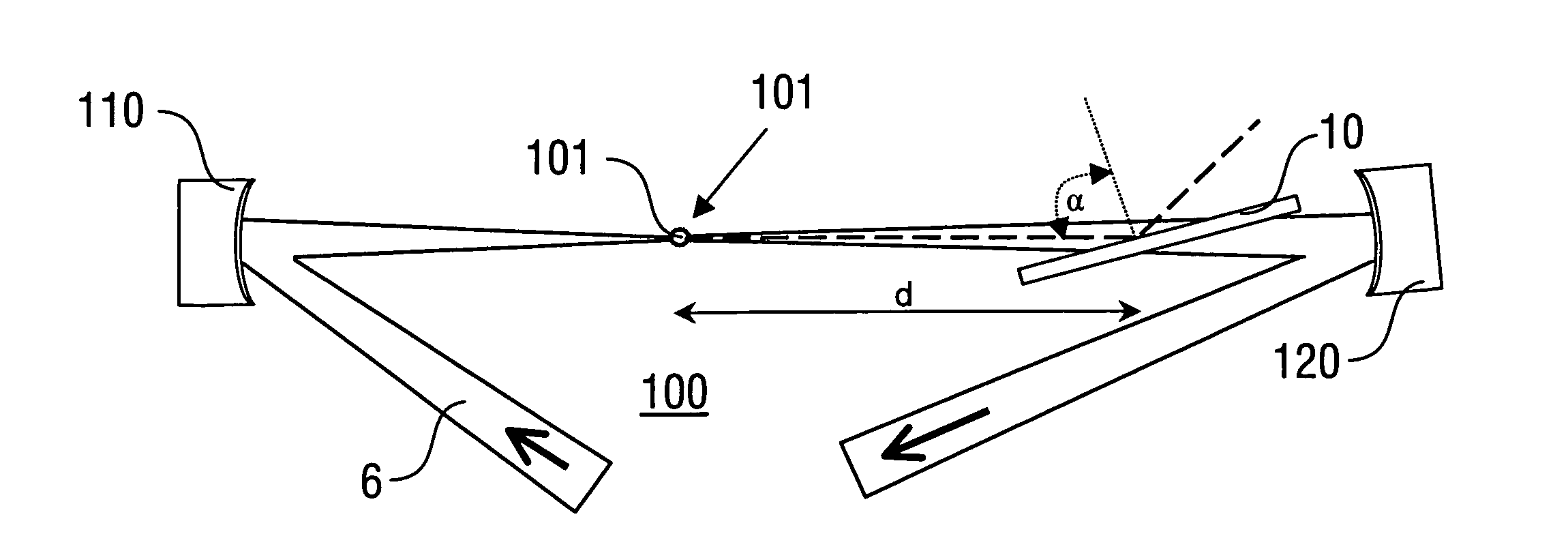
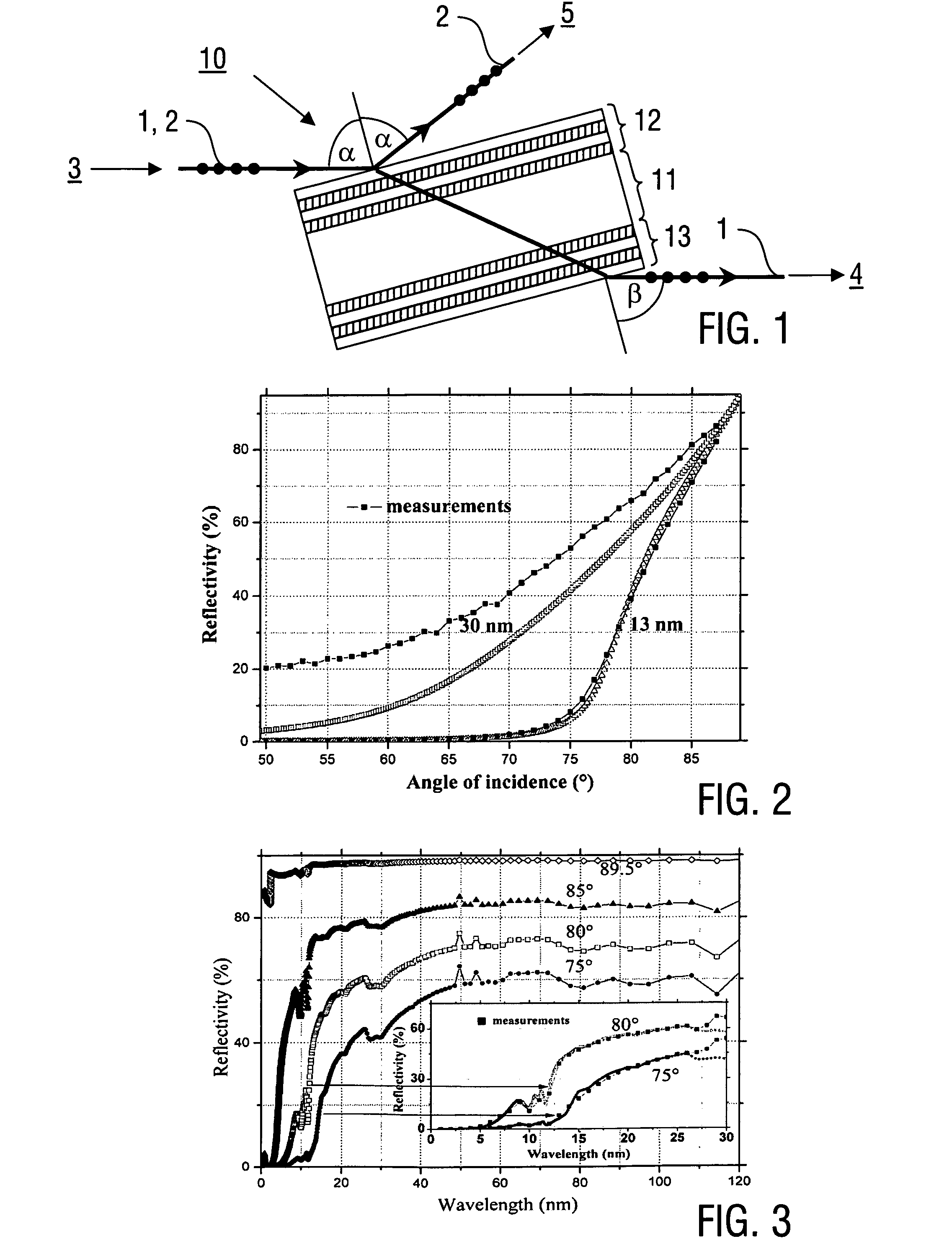
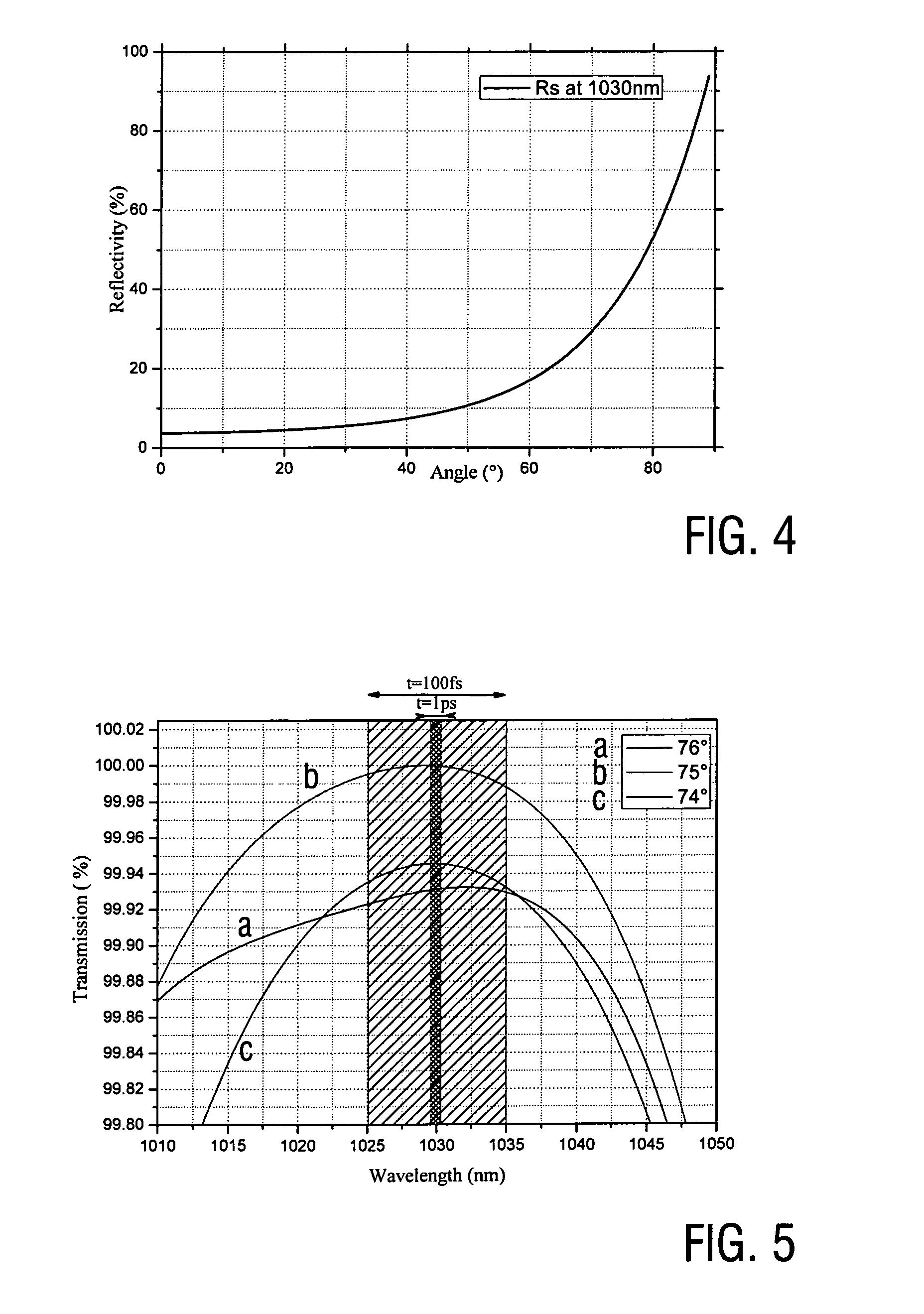
[0056]Embodiments of the invention are described in the following with particular reference to the design of the optical relaying device and the application thereof, in particular for output coupling of higher harmonic radiation from an enhancement cavity. Details of the cavity design or operation, in particular the HHG process is not described as it is known as such from prior art. It is emphasized that the invention is not restricted to the enhancement cavity application but rather can be implemented in an analogue manner e.g. in a XUV, UV, or VIS output coupling device for second or higher harmonics generated inside a high-power laser oscillator cavity or for separating the XUV, UV, or VIS from the fundamental radiation in single-pass systems. Generally, the enhancement cavity approach can be applied not only for generating XUV but also for any low-efficient nonlinear process creating new spectral components that does not affect the fundamental intracavity light. Therefore, this ...


PUM


Abstract

A method of spatially relaying a first radiation component (1) having a first wavelength and a second radiation component (2) having a second wavelength different from the first radiation component (1), using an optical relaying device (10) which comprises a transparent plate (11) having anti-reflection coatings (12, 13) on both side surfaces thereof, comprises transmitting the first radiation component (1) across the optical relaying device (10) with predetermined incident (a) and emergent angles (β), resp., wherein said anti-reflection coatings (12, 13) being effective for the first radiation component (1) at the incident and emergent angles (α, β), resp., and reflecting the second radiation component (2) at the optical relaying device (10) with a predetermined reflection angle (a) being equal to at least one of said incident and emergent angles (α, β), wherein the first and second radiation components (1, 2) are split from each other toward different directions or combined into a common beam path. Furthermore, an optical relaying device (10) and a resonator device, in particular enhancement cavity device (100) and a laser resonator, are described.

Description

FIELD OF THE INVENTION[0001]The present invention relates to a method of spatially relaying, in particular splitting or combining, radiation components with different wavelengths, like spatially relaying a first radiation component, which e.g. includes a fundamental wavelength in an optical wavelength range, and a second radiation component, which e.g. includes shorter wavelengths compared with the fundamental wavelength, in particular second or higher harmonic wavelengths relative to the fundamental wavelength. Furthermore, the present invention relates to a method of output coupling radiation from an optical resonator like e.g. an enhancement cavity or a laser resonator, to a method of conducting a pump-probe measurement, to an optical relaying device being capable of wavelength-selective relaying, in particular splitting or combining of radiation components, and to a resonator device, in particular an enhancement cavity or a laser resonator provided with the optical relaying devi...

Claims


Application Information

Patent Timeline
IPC IPC(8): G02B27/10H01S3/08G01N21/25
CPCG02B27/1006H01S3/08G01N21/25G02B5/283H01S3/08059H01S3/106
Inventor PRONIN, OLEGAPOLONSKIY, ALEXANDERKRAUSZ, FERENCPERVAK, VLADIMIR
Owner PRONIN OLEG
Why Eureka
Try Eureka