Nozzle plate, liquid ejecting head, liquid ejecting apparatus, and manufacturing method of nozzle plate

Active Publication Date: 2019-09-03
SEIKO EPSON CORP
View PDF6 Cites 0 Cited by
  • Summary
  • Abstract
  • Description
  • Claims
  • Application Information

AI Technical Summary

Benefits of technology

This patent describes a liquid ejecting apparatus with a nozzle plate having high abrasion resistance and liquid repellency. The nozzle plate is coated with a DLC film containing fluorine, which gradually decreases in concentration towards the base material. This results in a high fluorine content in the region along the nozzle opening, allowing for easy cleaning of the nozzle plate. Additionally, a region with lower fluorine concentration is created between the nozzle openings, preventing ink from accumulating there and ensuring stable ink droplet discharge. The provision of a durable and liquid-repellent nozzle plate is made possible through this configuration. The liquid ejecting apparatus described in this patent is also more durable than previous configurations.

Problems solved by technology

Although the DLC film had high hardness, since the nozzle plate of the liquid ejecting head described in JP-A-2012-91380 contained fluorine in the DLC film in order to obtain the liquid repellency, there was a possibility that the hardness was decreased to cause a problem in durability.
Therefore, for example, in a case where the ink aggregates on the nozzle plate and the hardness of the aggregate is high, there was a problem in abrasion resistance that the region along the nozzle opening is scraped by sliding between the wiper and the nozzle plate during maintenance.
On the contrary, in a case where the fluorine content of the DLC film is reduced in order to obtain the abrasion resistance, the liquid repellency of the surface of the DLC film is impaired.
That is, it has been difficult to obtain the nozzle plate that is compatible with the durability and the liquid repellency.
When the fluorine-containing DLC film formed in the forming is irradiated with the laser in the defect generating, a defect is generated in that portion.
Furthermore, when the nozzle plate is heated in the thermal annealing, fluorine is gathered in a defect portion.

Method used


Image

  • Nozzle plate, liquid ejecting head, liquid ejecting apparatus, and manufacturing method of nozzle plate
  • Nozzle plate, liquid ejecting head, liquid ejecting apparatus, and manufacturing method of nozzle plate
  • Nozzle plate, liquid ejecting head, liquid ejecting apparatus, and manufacturing method of nozzle plate

Examples


embodiment 1

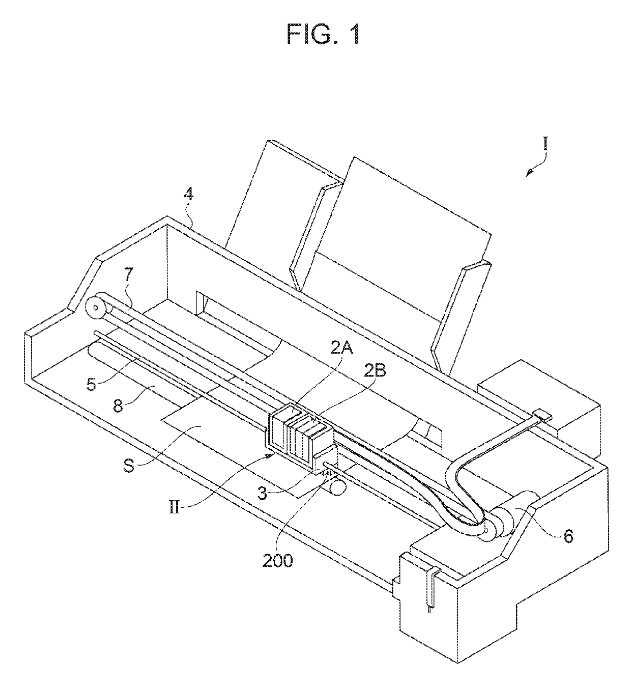
[0040]FIG. 1 is a view showing a schematic configuration of a liquid ejecting apparatus according to Embodiment 1.

[0041]As shown in FIG. 1, in the liquid ejecting apparatus I, in a head unit II having a plurality of liquid ejecting heads 200, cartridges 2A and 2B as ink supply means that supplies ink as a liquid to the liquid ejecting head 200 are detachably provided. A carriage 3 on which the head unit II is mounted is provided movably along an axial direction of a carriage shaft 5 attached to an apparatus main body 4. The liquid ejecting head 200 corresponding to the cartridges 2A and 2B ejects, for example, a black ink composition and a color ink composition. The ink supply means may be configured to supply the ink from an ink tank storing the ink with a tube.

[0042]A driving force of a drive motor 6 is transmitted to the carriage 3 through a plurality of gears (not shown) and a timing belt 7, so that the head unit II is moved with the carriage 3 along the carriage shaft 5. On the...

embodiment 2

[0087]FIG. 8 is a flowchart describing a manufacturing method of a nozzle plate according to Embodiment 2. FIGS. 9A and 9B are cross-sectional views partially enlarging the nozzle plate. FIG. 10 is a graph showing a distribution of a fluorine concentration in a surface of a DLC film. A manufacturing method different from that of Embodiment 1 of the nozzle plate 420 will be described with reference to FIGS. 8 to 10. The same constituent parts as those of Embodiment 1 are used by the same reference numerals, and redundant descriptions will be omitted. In addition, since steps S11 and S12 are the same as steps S1 and S2 described in Embodiment 1, description thereof will be omitted.

[0088]Step S13 is a forming step of a fluorine-containing DLC film 424 on a base material (silicon substrate 22) of a nozzle plate 420. In this embodiment, the fluorine-containing DLC film 424 containing a uniform fluorine concentration is formed. The fluorine-containing DLC film 424 can be formed by a CVD m...

modification example 1

[0094]FIG. 11 is a cross-sectional view partially enlarging a nozzle plate according to Modification Example 1. A configuration of a nozzle plate 520 will be described with reference to FIG. 11. The same constituent parts as those of Embodiment 1 are denoted by the same reference numerals, and redundant descriptions will be omitted.

[0095]In the nozzle plate 520, a region 525 having a fluorine concentration lower than that of the region B along the nozzle opening 21 is provided between the nozzle openings 21 adjacent to each other. In the nozzle plate 520 shown in this modification example, the region 525 having a low fluorine concentration is formed in the nozzle plate 20 described in Embodiment 1. As shown in FIG. 11, the region 525 having a thin film thickness of the fluorine-containing DLC film 24 is formed between the nozzle openings 21 adjacent to each other. Since the fluorine concentration of the fluorine-containing DLC film 24 is decreased in the direction from the surface o...


PUM


Abstract

A nozzle plate is a nozzle plate provided with a plurality of nozzle openings, in which a DLC film is provided on a base material (silicon substrate) of the nozzle plate, the DLC film contains fluorine, a fluorine concentration in the DLC film decreases in a direction from a surface of the DLC film toward the silicon substrate, and a fluorine concentration in a region along the nozzle opening is lower than a fluorine concentration in the surface of the DLC film (surface of flat portion).

Description

BACKGROUND1. Technical Field[0001]The present invention relates to a nozzle plate, a liquid ejecting head, a liquid ejecting apparatus, and a manufacturing method of the nozzle plate.2. Related Art[0002]In the related art, a liquid ejecting head that ejects liquid into liquid droplets has been known as an ink jet type recording head. The liquid ejecting head has a nozzle plate provided with a plurality of nozzle openings, and ejects the liquid droplets toward a recording medium from the nozzle opening. The nozzle plate is required to have liquid repellency to prevent the liquid droplets from adhering to a surface of the nozzle plate. For example, JP-A-2012-91380 discloses a droplet (liquid) ejecting head in which a side of an ejecting surface (liquid ejecting surface) of a nozzle plate is formed with fluorine-containing diamond-like carbon (DLC). As a result, it is disclosed that water repellency can be imparted to the surface of the nozzle plate. In addition, JP-A-2003-98305 also d...

Claims


Application Information

Patent Timeline
IPC IPC(8): B41J2/14B41J2/16
CPCB41J2/161B41J2/1628B41J2/14233B41J2/1433B41J2/1606B41J2/162B41J2/1623B41J2/1632B41J2/1642B41J2/1646B41J2002/14241B41J2002/14419B41J2/16B41J2/1634B41J2/164
Inventor TONOMURA, OSAMUSUZUKI, SATOSHI
Owner SEIKO EPSON CORP
Why Eureka
Try Eureka