
Electrically driven winch device and mobile crane

a winch device and electric drive technology, applied in mechanical energy handling, transportation and packaging, hoisting equipment, etc., can solve the problems of low energy efficiency of hydraulic actuators, inability to employ electrically driven winch devices having such structures, and large vehicle widths, etc., to achieve a large hoisting capacity and suppress the axial width of the winch drum

Inactive Publication Date: 2019-09-03
KOBE STEEL LTD +1
View PDF15 Cites 4 Cited by
  • Summary
  • Abstract
  • Description
  • Claims
  • Application Information

AI Technical Summary

Benefits of technology

The invention is a device that uses electric power to move a large winch. The goal is to make the device compact and still have a big lifting capacity. The patent describes a way to achieve this.

Problems solved by technology

However, a hydraulic actuator generally has low energy efficiency.
Accordingly, it becomes impossible to employ an electrically driven winch device having such a structure in a case where there is restriction regarding an installation space.
Moreover, when such an electrically driven winch device is mounted on a mobile crane, a vehicle width thereof becomes large, and it may possibly become necessary to employ disassembling transportation in transporting the mobile crane using a public road, according to a legal request on vehicle width limitation.

Method used


Image

  • Electrically driven winch device and mobile crane
  • Electrically driven winch device and mobile crane
  • Electrically driven winch device and mobile crane

Examples


Embodiment Construction

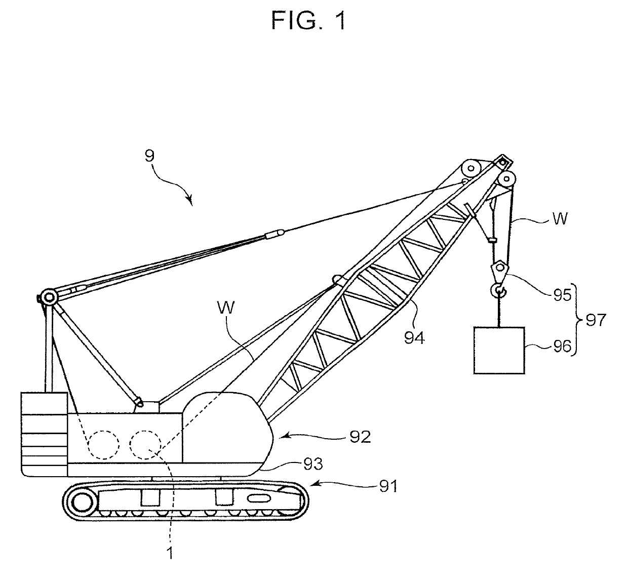
[0025]The following description will explain embodiments of the present invention in detail with reference to the drawings. FIG. 1 is a schematic side view of a mobile crane 9 having an electrically driven winch device 1 according to an embodiment of the present invention mounted thereon. The mobile crane 9 is a crawler crane and is provided with a self-travelling lower travelling body 91 of crawler type, and an upper slewing body 92 mounted on the lower travelling body 91.

[0026]The upper slewing body 92 is provided with a slewing frame 93 which is mounted on the lower travelling body 91 so as to be able to slew around a vertical axis, a boom 94 attached to a front part of the slewing frame 93 so as to be able to rise, and a hooking device 95 which is hung from a tip of the boom 94 via a wire rope W (a work rope) which is a hoisting rope. The hooking device 95 functions as an operation unit for hoisting work. FIG. 1 illustrates a state where a hoisted load 96 is hung by the hooking ...


PUM


Abstract

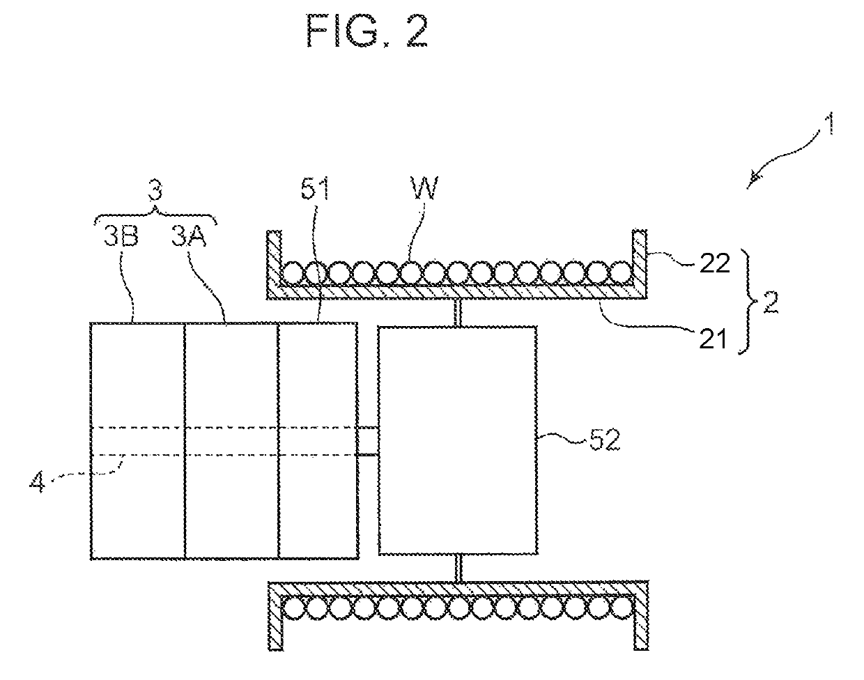
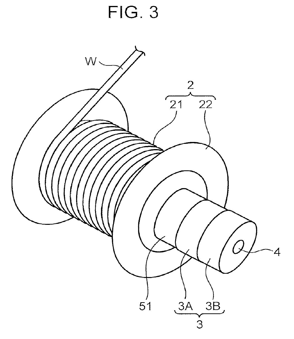
An electrically driven winch device includes a winch drum, a plurality of axial-gap electric motors, and a drive shaft. The winch drum rotates around a drum axis in order to wind or unwind a work rope. The plurality of electric motors are electric motors configured to drive the winch drum to rotate, and are each provided with a stator, and rotors which rotate around a rotation axis and are disposed at an axial distance from the stator. The drive shaft is disposed coaxially with the drum axis and serially connects the rotors of the plurality of electric motors on the rotation axis.

Description

TECHNICAL FIELD[0001]The present invention relates to an electrically driven winch device provided with a winch drum configured to wind and unwind a work rope, and a mobile crane provided with the electrically driven winch device.BACKGROUND ART[0002]A mobile crane is provided with a winch device configured to wind up and down a hoisted load. A mainly used winch device is a winch device driven by a hydraulic actuator such as a hydraulic motor. However, a hydraulic actuator generally has low energy efficiency. It is therefore proposed to mount, on a crane, an electrically driven winch device in which an electric actuator having relatively high energy efficiency is used as a driving source for the electrically driven winch device. For example, motorization of a winch device is progressing for a tower crane configured to perform crane work in a state fixed to a floor of a building under construction.[0003]Patent Literature 1 discloses a climbing crane which is an example of a tower cran...

Claims


Application Information

Patent Timeline
Patent Type & Authority Patents(United States)
IPC IPC(8): B66D1/12B66C23/36H02K21/24
CPCB66C23/36H02K21/24B66D1/12B66C2700/0378B66D2700/0141B66C13/26H02K7/14H02K1/2795
Inventor HIEKATA, TAKASHIINOUE, KOJIKAWAI, HIROAKISASAI, SHINTAROHOGAWA, TETSUYAYAMASHITA, TOSHIRO
Owner KOBE STEEL LTD
Learn More