
Optical fiber mode scrambler

a technology of optical fiber and modem, which is applied in the direction of fiber transmission, multimode transmission, optical waveguide light guide, etc., can solve the problems of high homogeneity of light at the output of optical fiber, and achieve the effects of low cost, high homogeneity of light, and space saving

Inactive Publication Date: 2019-09-03
UNIV DE LILLE +2
View PDF10 Cites 0 Cited by
  • Summary
  • Abstract
  • Description
  • Claims
  • Application Information

AI Technical Summary

Benefits of technology

The patent describes a device that scrambles the optical fibers in a mode that creates many bendings in three dimensions. This creates a high homogeneity of the light at the output of the fiber. The device is small, space-saving, and easy to carry, with a high number of micro-bendings and minimal length of fiber used.

Problems solved by technology

Such a mode scrambler creates many bendings on the optical fibers in the three dimensions, leading to a high homogeneity of the light at the output of the optical fiber.

Method used


Image

  • Optical fiber mode scrambler
  • Optical fiber mode scrambler
  • Optical fiber mode scrambler

Examples


Embodiment Construction

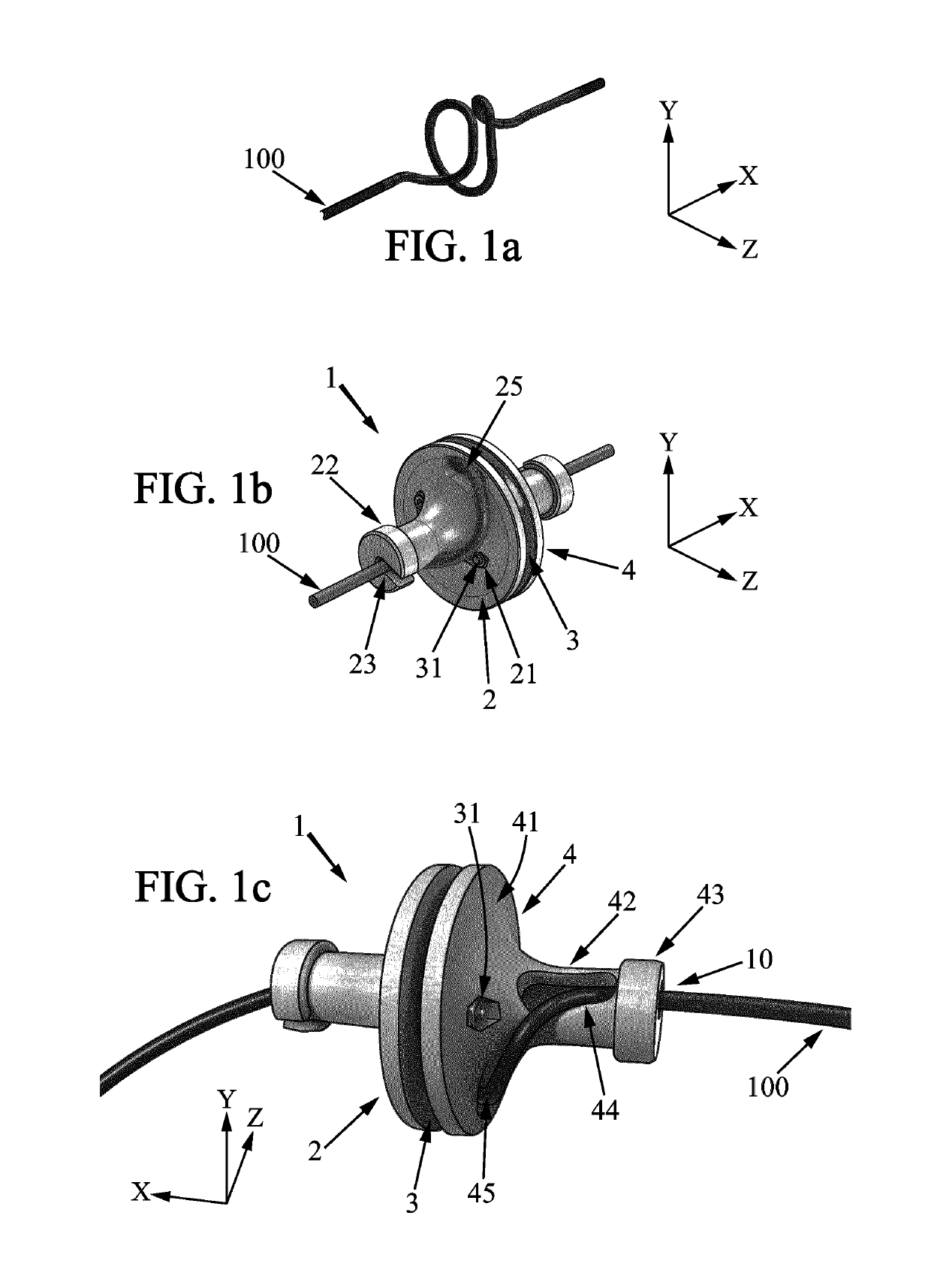
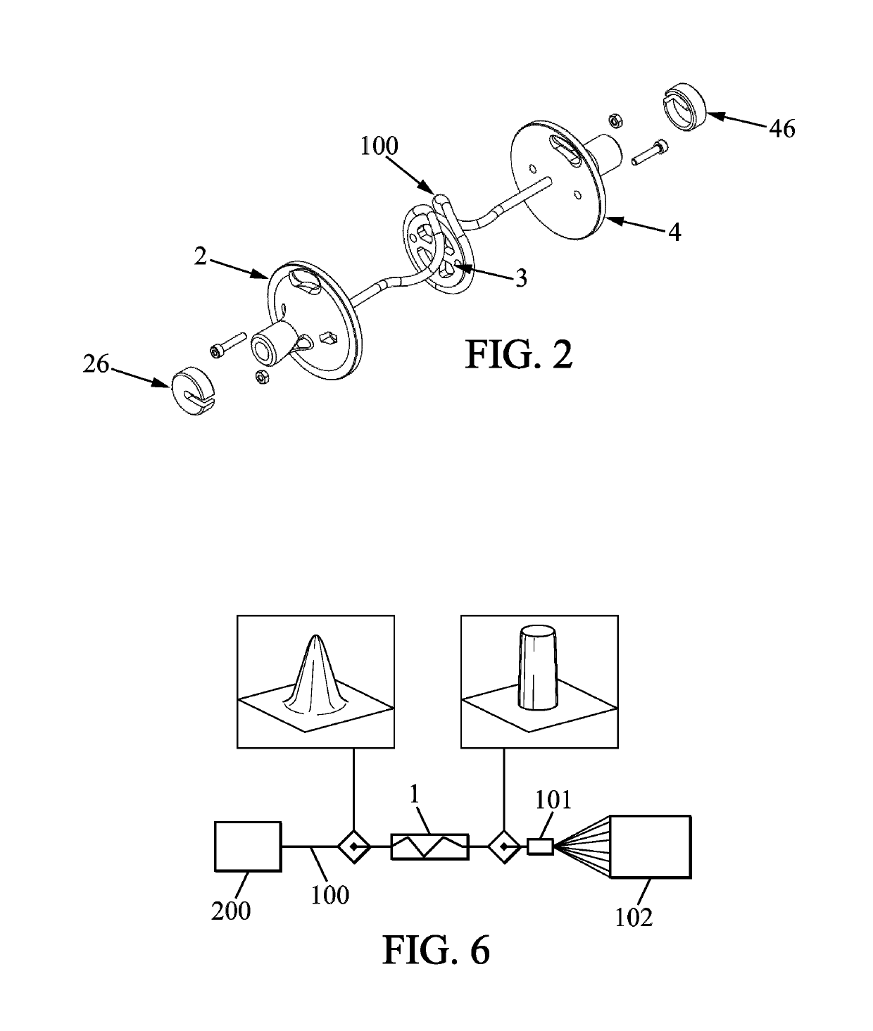
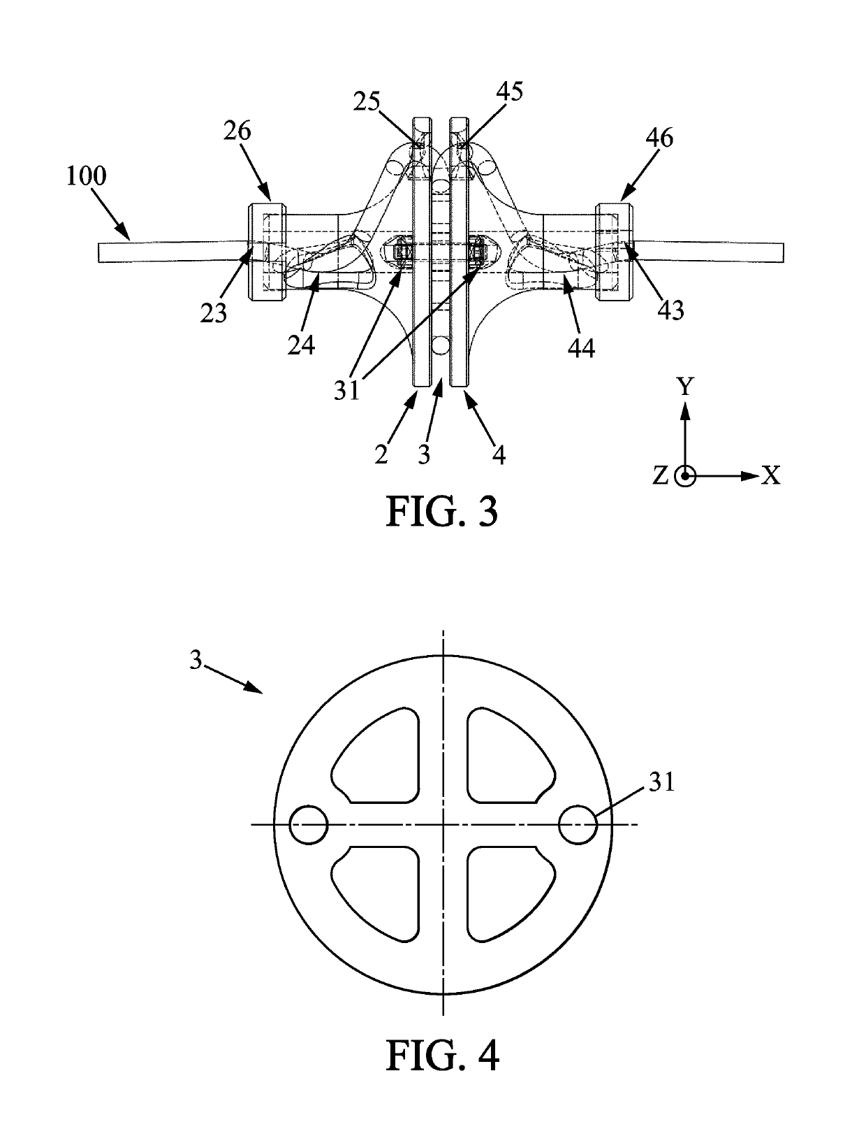
[0030]The object of the invention is an optical fiber mode scrambler 1 adapted to give a determined bending to an optical fiber inserted in the mode scrambler, as illustrated on FIG. 1a.

[0031]The mode scrambler device has a general extension direction X. The direction (−X) is defined as the direction parallel and in the opposed direction to the direction X. A direction Y is a direction transverse to the direction X. A direction Z being defined in such a way that the directions X, Y and Z form a right-handed orthogonal spatial system. The direction (−Y) is the direction parallel and in the opposed direction to the direction Y. The mode scrambler has a portion with a morphology adapted to give the optical fiber a direction along X at the entry of the scrambler. The mode scrambler has another portion with a morphology adapted to bend the fiber to bring the fiber substantially in the X, Y plane in the −X and Y directions. The mode scrambler has another portion with a morphology adapted...


PUM


Abstract

An optical fiber mode scrambler adapted to give a determined bending to an optical fiber inserted in the mode scrambler, the mode scrambler having a general extension direction X, the mode scrambler having a morphology adapted to give the optical fiber a direction along X at the entry of the scrambler, and then to bend the fiber to bring the fiber substantially in the X, Y plan in the -X and Y directions, before bringing the fiber in a rotation around the X axis substantially in the Y, Z plan in the anti clockwise direction for one full rotation, and then bending the fiber to bring the fiber substantially in the X, Y plan in the -X and -Y directions, and then bending the fiber to give the optical fiber a direction along X at the exit of the scrambler.

Description

BACKGROUND OF THE INVENTION[0001]The prior art document US2006 / 0222305 describes a helical optical fiber mode scrambler. The three-dimensional spiral curvature given to the optical fiber induces mode coupling in the optical fiber, to improve the uniformity of the light intensity at the output. However, the light signal at the output of the fiber using this mode scrambler is still inhomogeneous. Moreover, the helical optical fiber mode scrambler is a long piece (to get enough bendings for a good redistribution of the light) and is cumbersome.[0002]One needs a mode scrambler as compact and easy to handle as possible (adapted to be used for experimentation set up for example) and adapted to provide an homogeneous light intensity at the output of an optical fiber inserted in the scrambler.[0003]It is an object of the invention to provide an optical fiber mode scrambler device adapted to provide a significant mode scrambling of an optical fiber associated to it.SUMMARY OF THE INVENTION[0...

Claims


Application Information

Patent Timeline
Patent Type & Authority Patents(United States)
IPC IPC(8): G02B6/02G02B6/14H04B10/2581
CPCG02B6/14H04B10/2581
Inventor MORDON, SERGEDELEPÔRTE, PASCALBETROUNI, NACIMDELEPORTE, PASCAL
Owner UNIV DE LILLE
Learn More