Multijunction solar cell assembly for space applications

a solar cell and multi-junction technology, applied in the field of solar cells and the fabrication of solar cells, can solve the problems of increasing the power out or solar cell efficiency, and being more complex to manufactur

Active Publication Date: 2019-09-03
SOLAERO TECH CORP
View PDF91 Cites 2 Cited by
  • Summary
  • Abstract
  • Description
  • Claims
  • Application Information

AI Technical Summary

Benefits of technology

[0020]It is an object of the present disclosure to provide increased photoconversion efficiency in a multijunction solar cell for space applications over the operational life of the photovoltaic power system.
[0021]It is another object of the present disclosure to provide in a multijunction solar cell in which the selection of the composition of the subcells and their band gaps maximizes the efficiency of the solar cell at a predetermined high temperature (in the range of 40 to 70 degrees Centigrade) in deployment in space at AM0 at a predetermined time after the initial deployment, such time being at least one, five, ten, fifteen, or twenty years.

Problems solved by technology

Compared to silicon, III-V compound semiconductor multijunction devices have greater energy conversion efficiencies and generally more radiation resistance, although they tend to be more complex to manufacture.
The overall power output and conversion efficiency of the solar cell are thereby affected in different and often unpredictable ways.
Accordingly, it is evident that the consideration of any one design parameter or variable, such as the amount of a particular constituent element in a layer, or the band gap of that layer, affects each of the electrical characteristics in a different way, sometimes in opposite directions, and such changes does not predictably lead to an increase in power out or solar cell efficiency.
Stated another way, focus on any one such parameter in the design of a multijunction solar cell is not a viable calculus since each variable standing alone is NOT a simple “result effective” variable that can be automatically adjusted by those skilled in the art confronted with complex design specifications and practical operational considerations in order to achieve greater power output or a related design objective.

Method used


Image

  • Multijunction solar cell assembly for space applications
  • Multijunction solar cell assembly for space applications
  • Multijunction solar cell assembly for space applications

Examples


first embodiment

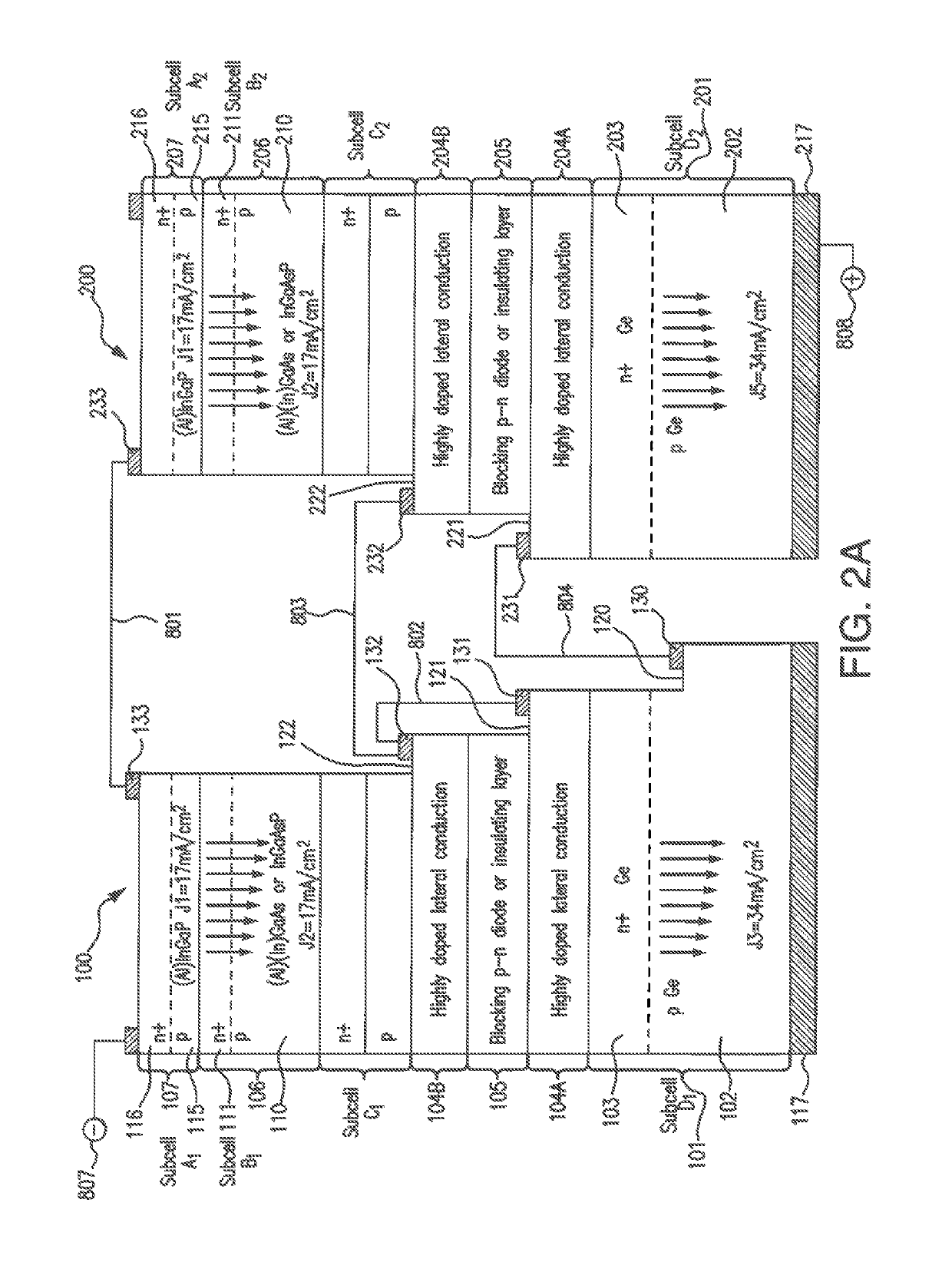
[0128]Turning to the fabrication of the multijunction solar cell assembly of the present disclosure, and in particular a five-junction solar cell assembly, FIG. 2A is a cross-sectional view of a solar cell assembly comprising two four junction solar cell subassemblies 100 and 200 after several stages of fabrication including the growth of certain semiconductor layers on the growth substrate, and formation of grids and contacts on the contact layers of the semiconductor bodies, and interconnection of the two subassemblies 100 and 200.

[0129]As illustrated in FIG. 2A, similar to that presented in related application Ser. No. 15 / 213,594, a first solar cell subassembly 100 includes multiple solar subcells in a tandem stack. In the illustrated example, the subassembly 100 includes an upper first subcell 107 (Subcell A1), a second middle solar subcell 106 (Subcell B1) disposed adjacent to and lattice matched to the upper first subcell 107, a third middle subcell 108 (Subcell C1), and a bot...

second embodiment

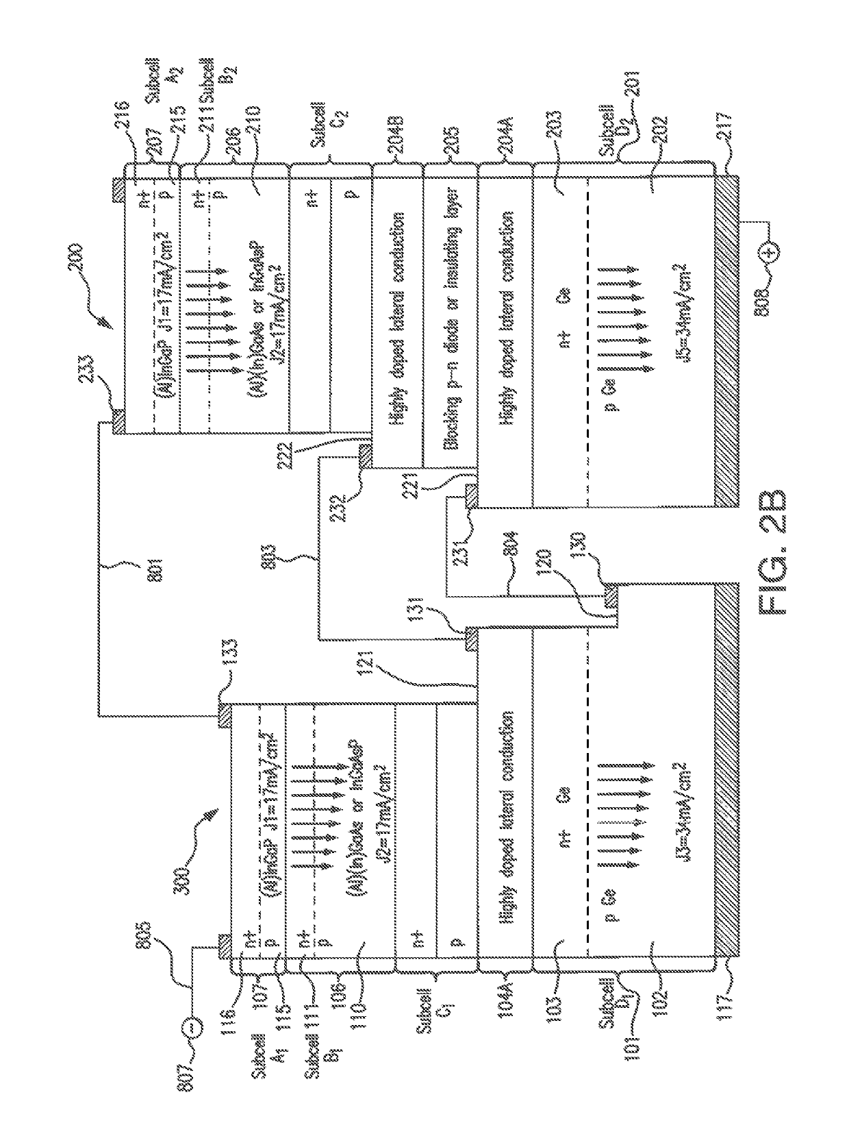
[0151]Turning to the fabrication of the multijunction solar cell assembly of the present disclosure, and in particular a five-junction solar cell assembly, FIG. 2B is a cross-sectional view of a solar cell assembly comprising two four junction solar cell subassemblies 300 and 200 after several stages of fabrication including the growth of certain semiconductor layers on the growth substrate, and formation of grids and contacts on the contact layers of the semiconductor bodies, and interconnection of the two subassemblies 300 and 200.

[0152]The second embodiment depicted in FIG. 2B includes a left subassembly 300 which has a sequence of layers which is substantially identical to subassembly 100 of FIG. 2A, except that layers 105 and 104B are omitted, while the right subassembly 200 depicted in FIG. 2B is identical to subassembly 200 of FIG. 2A. Therefore in the interest of brevity of this disclosure, the description of the identical layers in left subassembly 300 and right subassembly...


PUM


Abstract

A multijunction solar cell assembly and its method of manufacture including first and second discrete and different semiconductor body subassemblies which are electrically interconnected to form a five junction solar cell, each semiconductor body subassembly including first, second, third and fourth lattice matched subcells; wherein the average band gap of all four cells in each subassembly is greater than 1.44 eV.

Description

REFERENCE TO RELATED APPLICATIONS[0001]The present application claims the benefit of U.S. Provisional Patent Application Ser. Nos. 62 / 243,239 filed Oct. 19, 2015 and 62 / 288,181 filed Jan. 28, 2016.[0002]The present application is related to U.S. patent application Ser. No. 15 / 203,975 filed Jul. 7, 2016, and U.S. patent application Ser. No. 15 / 250,643 filed simultaneously hereto.[0003]This application is also related to co-pending U.S. patent application Ser. No. 15 / 210,532 filed Jul. 14, 2016, and Ser. No. 15 / 213,594 filed Jul. 19, 2016.[0004]This application is also related to co-pending U.S. patent application Ser. No. 14 / 660,092 filed Mar. 17, 2015, which is a division of U.S. patent application Ser. No. 12 / 716,814 filed Mar. 3, 2010, now U.S. Pat. No. 9,018,521; which was a continuation in part of U.S. patent application Ser. No. 12 / 337,043 filed Dec. 17, 2008.[0005]This application is also related to co-pending U.S. patent application Ser. No. 13 / 872,663 filed Apr. 29, 2012, wh...

Claims


Application Information

Patent Timeline
Patent Type & Authority Patents(United States)
IPC IPC(8): H01L31/0725H01L31/0304H01L31/05H01L31/18H01L31/0687
CPCH01L31/0504H01L31/0687H01L31/03046H01L31/1844H01L31/0725Y02P70/521Y02E10/544Y02P70/50
Inventor DERKACS, DANIELSTEINFELDT, JEFF
Owner SOLAERO TECH CORP
Why Eureka
Try Eureka