

Multijunction solar cell assembly
a solar cell and multi-junction technology, applied in the direction of basic electric elements, electrical apparatus, semiconductor devices, etc., can solve the problems of complex interdependence, complex and often unpredictable ways, and the difficulty of properly specifying and manufacturing, and achieve the effect of increasing the photoconversion efficiency
- Summary
- Abstract
- Description
- Claims
- Application Information
AI Technical Summary
Benefits of technology
Problems solved by technology
Method used
Image

Examples
first embodiment
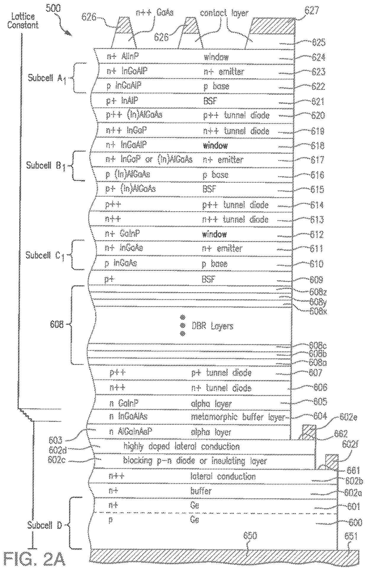
[0147]Turning to the fabrication of the multijunction solar cell assembly of the present disclosure, and in particular a five junction solar cell assembly, FIG. 2A is a cross-sectional view of a four junction solar cell subassembly 500 after several stages of fabrication including the growth of certain semiconductor layers on the growth substrate, and formation of grids and contacts on the contact layer of the semiconductor body.
[0148]As shown in the illustrated example of FIG. 2A, the bottom subcell D1 includes a substrate 600 formed of p-type germanium (“Ge”) in some embodiments, which also serves as a base layer. A back metal contact pad 650 formed on the bottom of base layer 600 provides electrical contact 651 to the multijunction solar cell subassembly 500.
[0149]In some embodiments, the contact 651 may be in the interior of the region 600 and not on the bottom surface of the region 600.
[0150]In some embodiments, the bottom subcell D1 is germanium, while in other embodiments the...
second embodiment
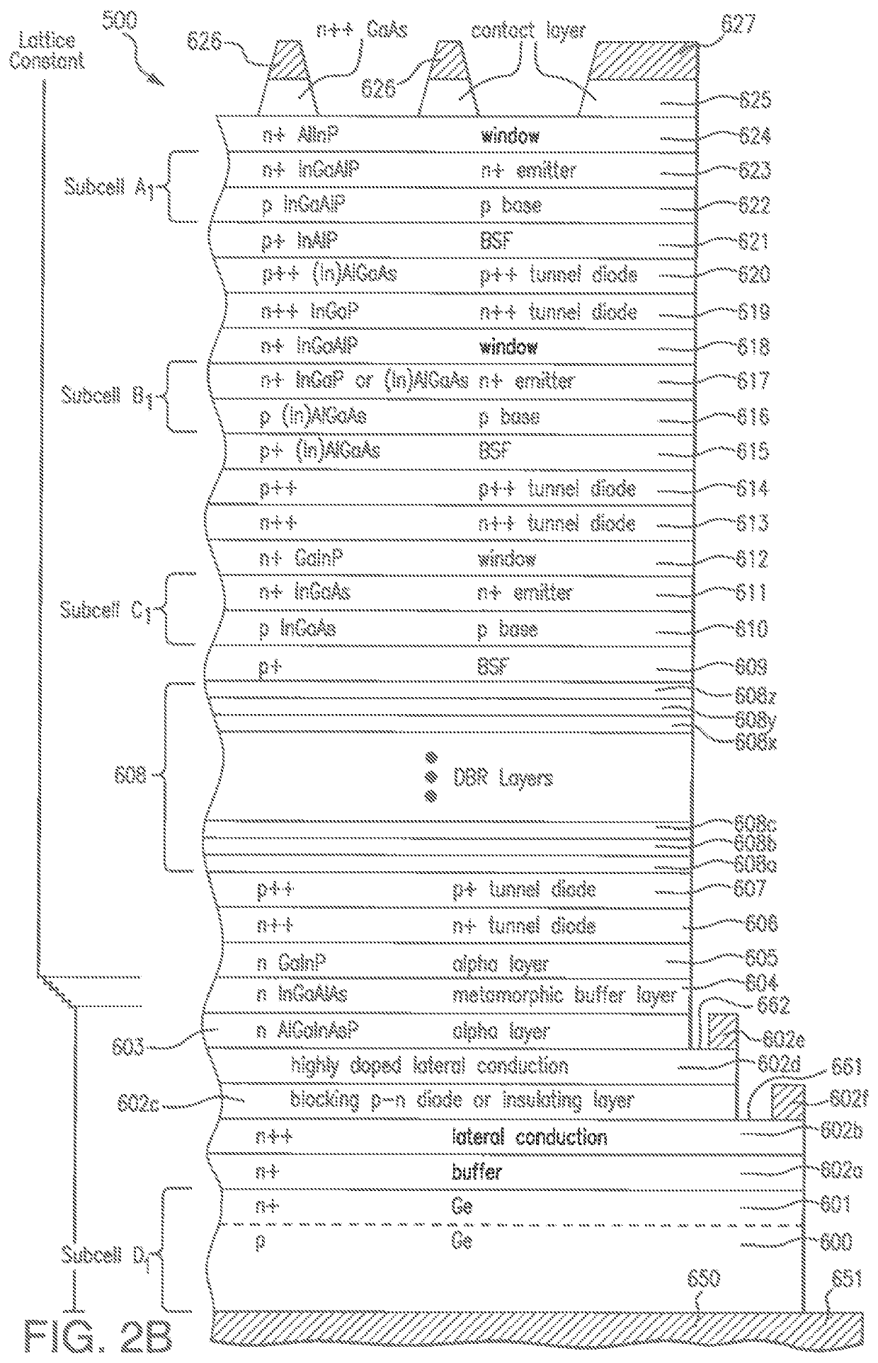
[0191]the second solar cell subassembly similar to that of FIG. 2C is another configuration (not shown) with that the metamorphic buffer layer 604 is disposed above the tunnel diode layers 706, 707 and below the DBR layers 708 (not illustrated).
[0192]The foregoing multijunction solar cell subassemblies 500, 600, or 700 can be fabricated, for example, in wafer-level processes and then singulated or diced into individual semiconductor chips. The various semiconductor layers can be grown, one atop another, using known growth techniques (e.g., MOCVD) as discussed above.
[0193]Each solar cell subassembly 500, 600 and 700 also can include grid lines, interconnecting bus lines, and contact pads. The geometry and number of the grid lines, bus lines and / or contacts may vary in other implementations.
[0194]As previously mentioned, two (or more) solar cell subassemblies (e.g., 500 and 700) or chips can be disposed adjacent and parallel to one another and connected together electrically. For exam...
PUM
| Property | Measurement | Unit |
|---|---|---|
| temperature | aaaaa | aaaaa |
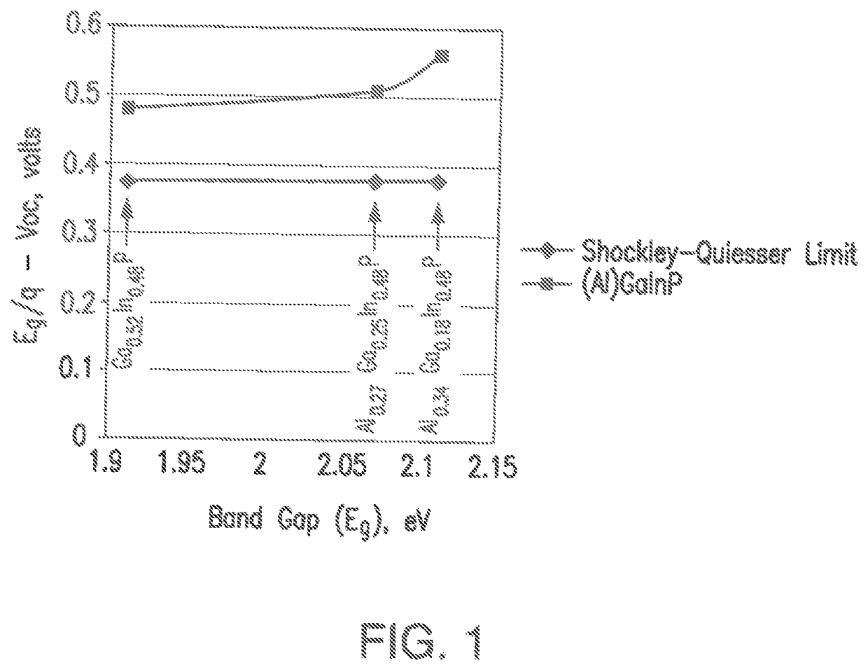
| band gap | aaaaa | aaaaa |
| band gap | aaaaa | aaaaa |
Abstract
Description
Claims
Application Information