
Dual-frequency downlink transmitter

a transmitter and dual-frequency technology, applied in the field of transmitters, can solve the problems of increasing the amount of hardware used in the transmitter implementation, occupying space on the respective transmitter board, and a lot of hardware to be fed with power, so as to reduce the amount of hardware in the transmitter

Active Publication Date: 2019-09-10
AIRBUS DEFENCE & SPACE
View PDF8 Cites 0 Cited by
  • Summary
  • Abstract
  • Description
  • Claims
  • Application Information

AI Technical Summary

Benefits of technology

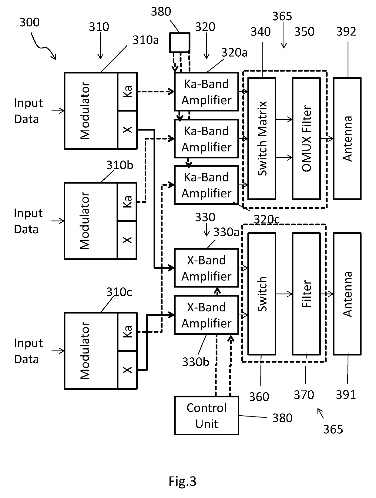
[0004]Thus, it is an object of the present invention to reduce the amount of hardware in a transmitter.
[0007]This has the advantage of minimizing input data and minimizing the amount of memory used for providing the input data.
[0008]The respective input data can be the same or different for each of the plurality of modulators. This can further minimize an amount of memory to be used for providing the input data to the transmitter.
[0018]This has the advantage to maximize an output in a respective frequency band. Thus, power can be reduced by minimizing a bandwidth or using orthogonality of transmitted electromagnetic waves.
[0022]Hereby, deterioration can be minimized by switching between different amplifiers. Thus, life expectancy of Ka-Band and X-Band amplifiers is increased.

Problems solved by technology

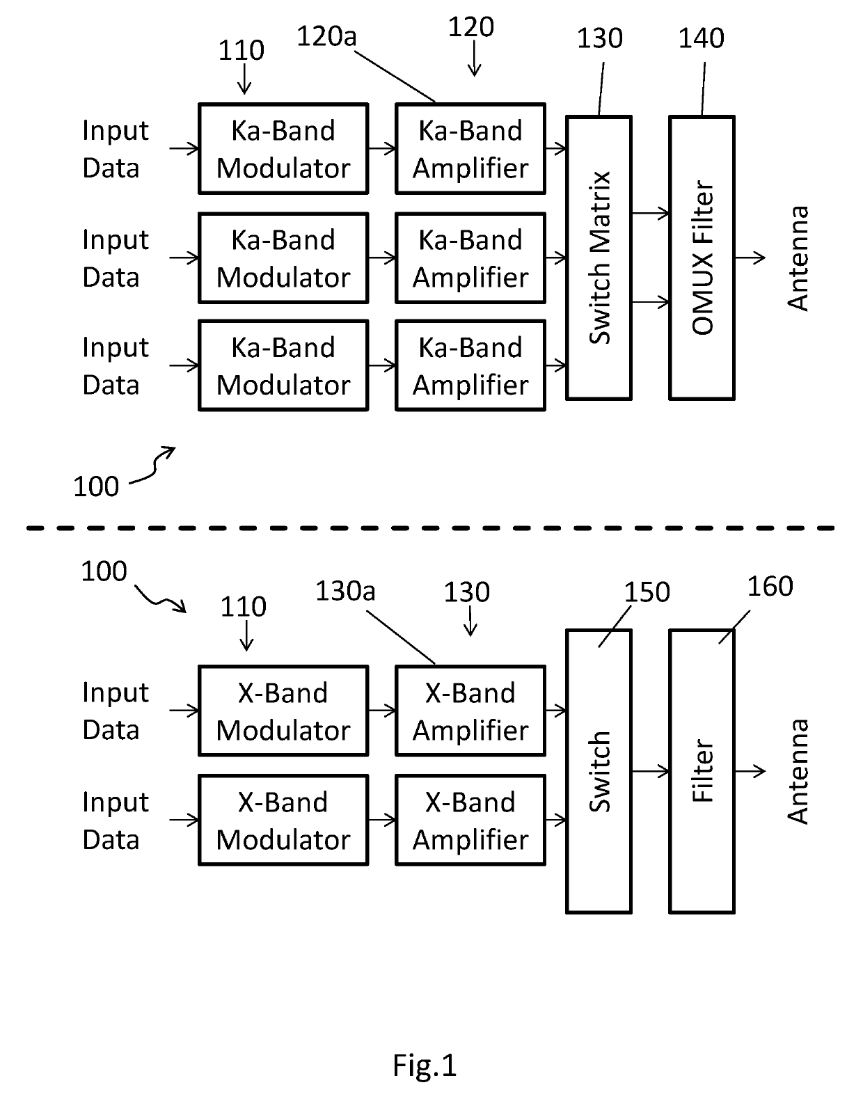
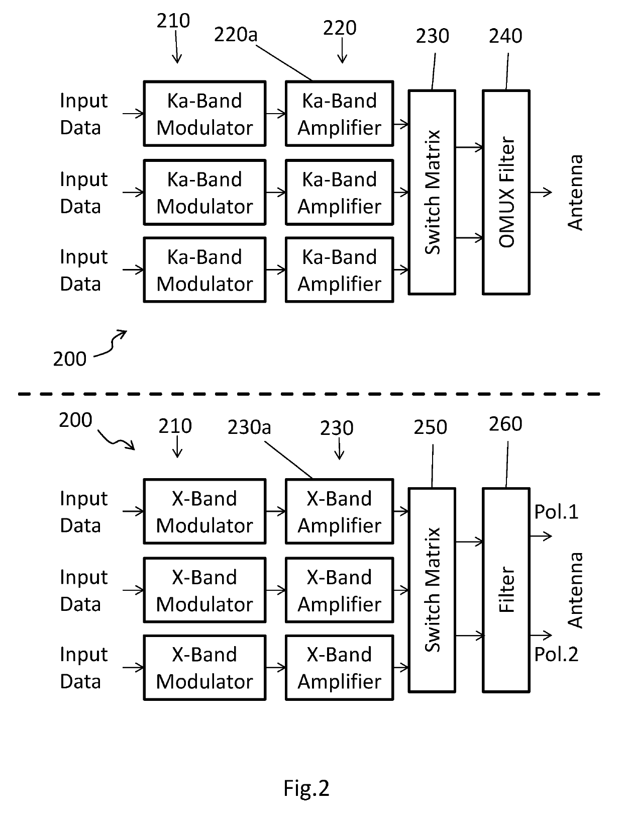
In downlink systems from a satellite to earth, X-Band and Ka-Band frequencies are used to be transmitted via two separated transmission paths separated from each other underlying the disadvantage of having a lot of hardware to be fed with power and occupying space on a respective transmitter board.
However, current implementations of transmitters in satellites still provide for each separate channel separate input data and separate modules, such that each transmission channel works independent of each other, which increases the amount of hardware used in the transmitter implementation.

Method used


Image

  • Dual-frequency downlink transmitter
  • Dual-frequency downlink transmitter
  • Dual-frequency downlink transmitter

Examples


Embodiment Construction

[0031]The variants of the functional and operational aspects, as well as their functional and operational aspects described herein, are only for a better understanding of its structure, its functions and properties; they do not limit the disclosure to the embodiments. The figures are partially schematic, the essential properties and effects are clearly shown enlarged or scaled down in part to clarify the functions, active principles, embodiments and technical characteristics. Every operation, every principle, every technical aspect and every feature that / which is disclosed in the figures or in the text is / can be combined with all claims, each feature in the text and the other figures, other modes of operation, principles, technical refinements and features that are included in this disclosure, or result from it, so that all possible combinations are assigned to the devices and methods described. They also include combinations of all individual comments in the text, that is, in each ...


PUM


Abstract

A transmitter for a dual-frequency satellite-to-earth downlink. The transmitter comprises a plurality of modulators, a first and a second plurality of amplifiers. In one embodiment, each of the modulators is configured to modulate respective input data onto a respective one of a first plurality of signals in a first frequency band and to modulate the respective one of the first plurality of signals onto a respective one of a second plurality of signals in a second frequency band. Each of the first plurality of amplifiers is configured to amplify one of the first plurality of signals to a first predetermined signal strength. Each of the second plurality of amplifiers is configured to amplify one of the second plurality of signals to a second predetermined signal strength. A number of the plurality of modulators is smaller than a sum of a number of the first and second pluralities of amplifiers.

Description

CROSS-REFERENCES TO RELATED APPLICATIONS[0001]This application claims the benefit of the European patent application No. 17168651.2 filed on Apr. 28, 2017, the entire disclosures of which are incorporated herein by way of reference.BACKGROUND OF THE INVENTION[0002]The present disclosure is directed to a transmitter for a dual-frequency satellite-to-earth downlink.[0003]In downlink systems from a satellite to earth, X-Band and Ka-Band frequencies are used to be transmitted via two separated transmission paths separated from each other underlying the disadvantage of having a lot of hardware to be fed with power and occupying space on a respective transmitter board. The respective transmitter board itself should be very small with respect to the satellite's payload parameters, such that hardware minimization in terms of size is a driving goal in satellite construction. However, current implementations of transmitters in satellites still provide for each separate channel separate input ...

Claims


Application Information

Patent Timeline
Patent Type & Authority Patents(United States)
IPC IPC(8): H04B7/185H04B7/10H04L25/02H04B1/00H04B1/04
CPCH04B7/18513H04B1/0064H04L25/0278H04B7/10H04B7/18515H04B1/0458
Inventor LANG, RAINER
Owner AIRBUS DEFENCE & SPACE
Learn More