Apparatus and method for release agent application and cleaning of a fuser surface using a release agent impregnated web

a release agent and web technology, applied in the field of electrographic printers, can solve the problems of local abrasion that degrades the fuser surface, and achieve the effects of improving the lifetime, improving the application rate, and improving the life of the release agen

Active Publication Date: 2009-05-14
XEIKON MFG NV
View PDF14 Cites 7 Cited by
  • Summary
  • Abstract
  • Description
  • Claims
  • Application Information

AI Technical Summary

Benefits of technology

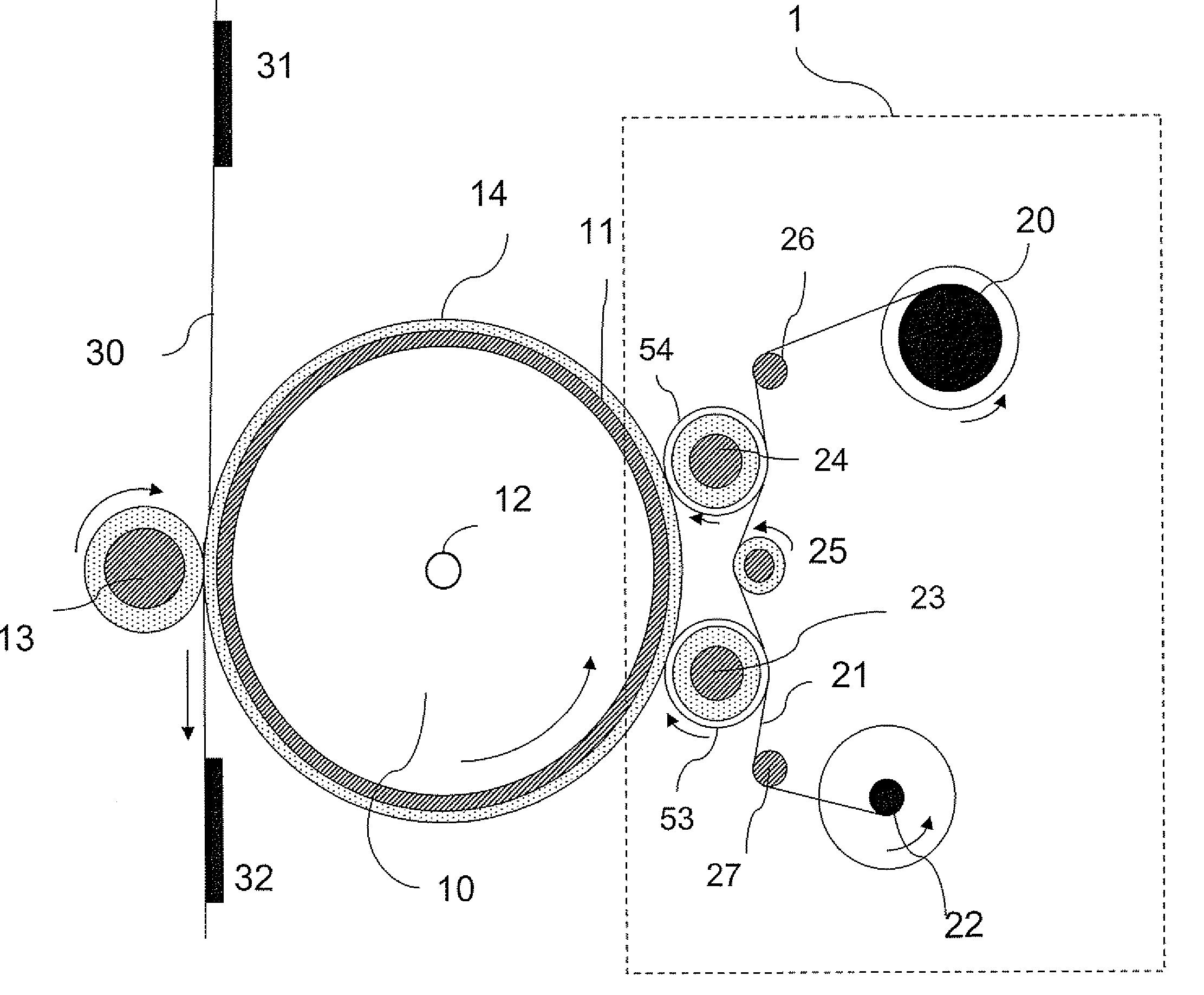
[0028]The above arrangement has the advantage that less release agent can be transferred to the printed images or at least the amount of release agent can be better controlled. The use of a release agent improves the lifetime. The slow advancement speed of the web increases the times between replacement, i.e. reduces downtime.
[0029]A further cleaning means can be provided to remove toner contaminants and / or paper debris from the cleaning roller. Such means can be a separate web or a scraper system or even it can be the same web as the release agent web. This provides a more optimal use of space, reduction of the number of replaceable components and reduction in the amount of hardware needed

Problems solved by technology

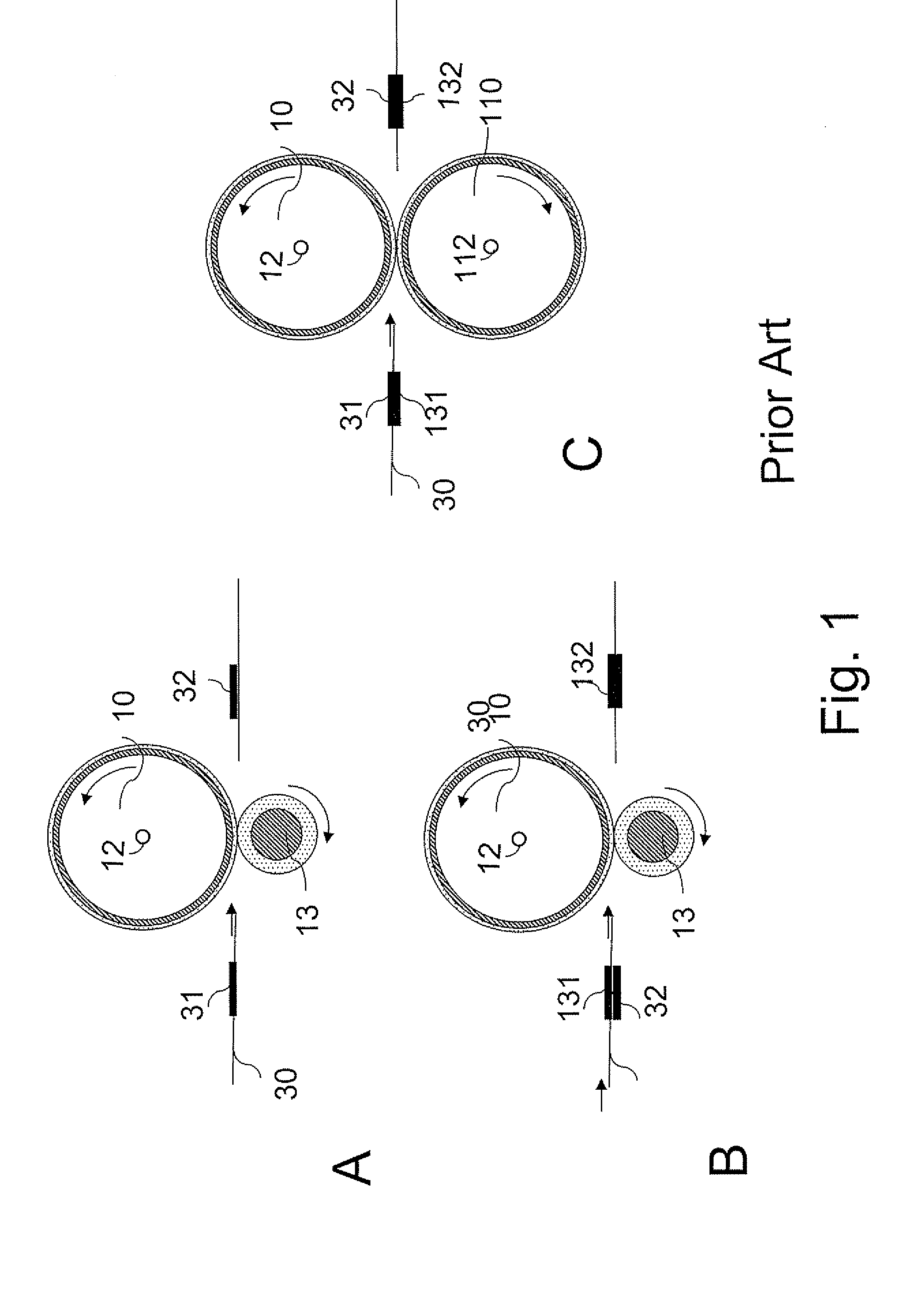
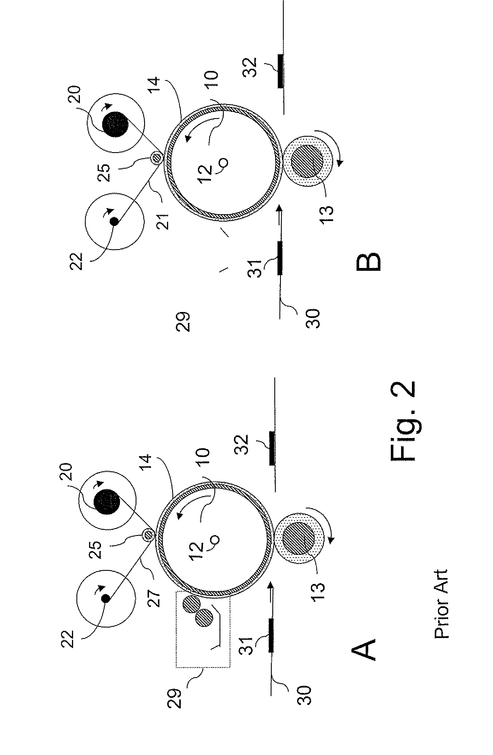
The nearly stationary web may accumulate contaminants such as paper debris that remain trapped and stationary in the contact area with the fusing surface of the rotating fuser roller or fusing or transfusing belt, and cause local abrasion that degrades the fusing surface.
Moreover debris and toner contaminants may still degrade the fuser surface (14) and such contaminants trapped between the web (21) and the fusing surface (14) interfere with the uniform release agent delivery giving rise to visible streaks of release agent on the final print that affect the uniformity of the gloss of the print as discussed in U.S. Pat. No. 6,449,455.

Method used


Image

  • Apparatus and method for release agent application and cleaning of a fuser surface using a release agent impregnated web
  • Apparatus and method for release agent application and cleaning of a fuser surface using a release agent impregnated web
  • Apparatus and method for release agent application and cleaning of a fuser surface using a release agent impregnated web

Examples


Embodiment Construction

[0055]The present invention will be described with respect to particular embodiments and with reference to certain drawings but the invention is not limited thereto but only by the claims. The drawings described are only schematic and are non-limiting. In the drawings, the size of some of the elements may be exaggerated and not drawn on scale for illustrative purposes. The dimensions and the relative dimensions do not correspond to actual reductions to practice of the invention.

[0056]Furthermore, the terms first, second, third and the like in the description and in the claims, are used for distinguishing between similar elements and not necessarily for describing a sequence, either temporally, spatially, in ranking or in any other manner. It is to be understood that the terms so used are interchangeable under appropriate circumstances and that the embodiments of the invention described herein are capable of operation in other sequences than described or illustrated herein.

[0057]More...


PUM


Abstract

An apparatus and method to condition the fuser surface of a fusing or transfusing apparatus for a toner based printing system is described. The apparatus and method integrate the functions of cleaning paper debris and residual toner from the fuser (or transfuse) surface on one hand and the application of a release agent such as silicone oil on the other hand using a single release agent impregnated web. The inventive device includes a release agent application roller and a cleaning roller where the outer surfaces and are selected in preferred embodiments for their respective wetting properties with respect to the release agent used. The fuser surface conditioning device increases the useful life for a fusing or transfusing roll or belt even when low amounts of release agent are applied to the fusing surface such that the amount of release agent that is transferred to the print media is in the range of 0.5 to 5 mg/A4 sheet.

Description

[0001]The present invention relates to a fusing or transfusing apparatus for a toner based printing, fax or copying system and a method for conditioning a fuser (or transfuse) surface of said fusing apparatus or transfusing apparatus as well as to a printer, fax or copier using the fusing or transfusing apparatus and to a method of printing using the conditioning method. The apparatus and method can integrate the functions of cleaning paper debris and residual toner from the fuser (or transfuse) surface on one hand and the application of a release agent such as silicone oil on the other hand using a single release agent impregnated web.TECHNICAL BACKGROUND[0002]With a conventional electrophotographic printer, a charging device charges the surface of a photoconductive drum or belt and an exposing unit such as an LED head writes an electrostatic latent image on the charged surface of the photoconductive drum. The electrostatic latent image is developed with toner into a toner image, w...

Claims


Application Information

Patent Timeline
Patent Type & Authority Applications(United States)
IPC IPC(8): G03G15/20
CPCG03G15/2025G03G2215/2093
Inventor ACHTEN, MAARTENMAMPAEY, KURTBRODDIN, DIRKVAN WEVERBERG, ERIC
Owner XEIKON MFG NV
Why Eureka
Try Eureka