Method and system for efficient cache locking mechanism

Active Publication Date: 2006-12-07
TOSHIBA ELECTRONICS DEVICES & STORAGE CORPORARTION +1
View PDF4 Cites 7 Cited by
  • Summary
  • Abstract
  • Description
  • Claims
  • Application Information

AI Technical Summary

Benefits of technology

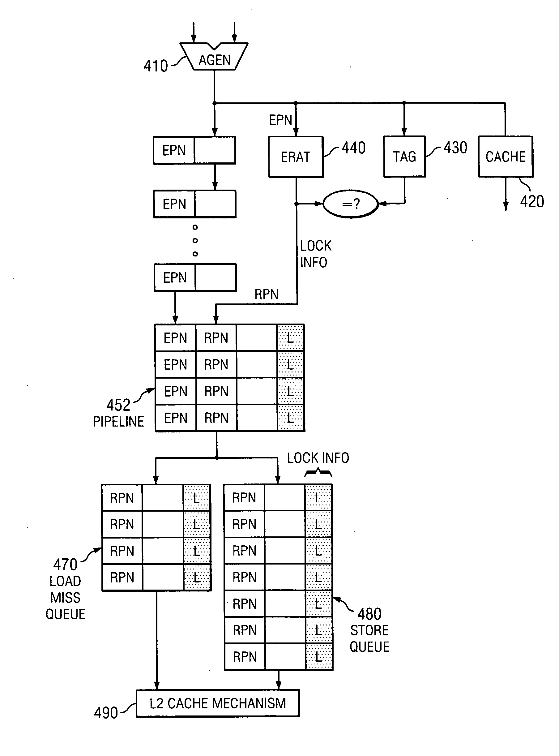
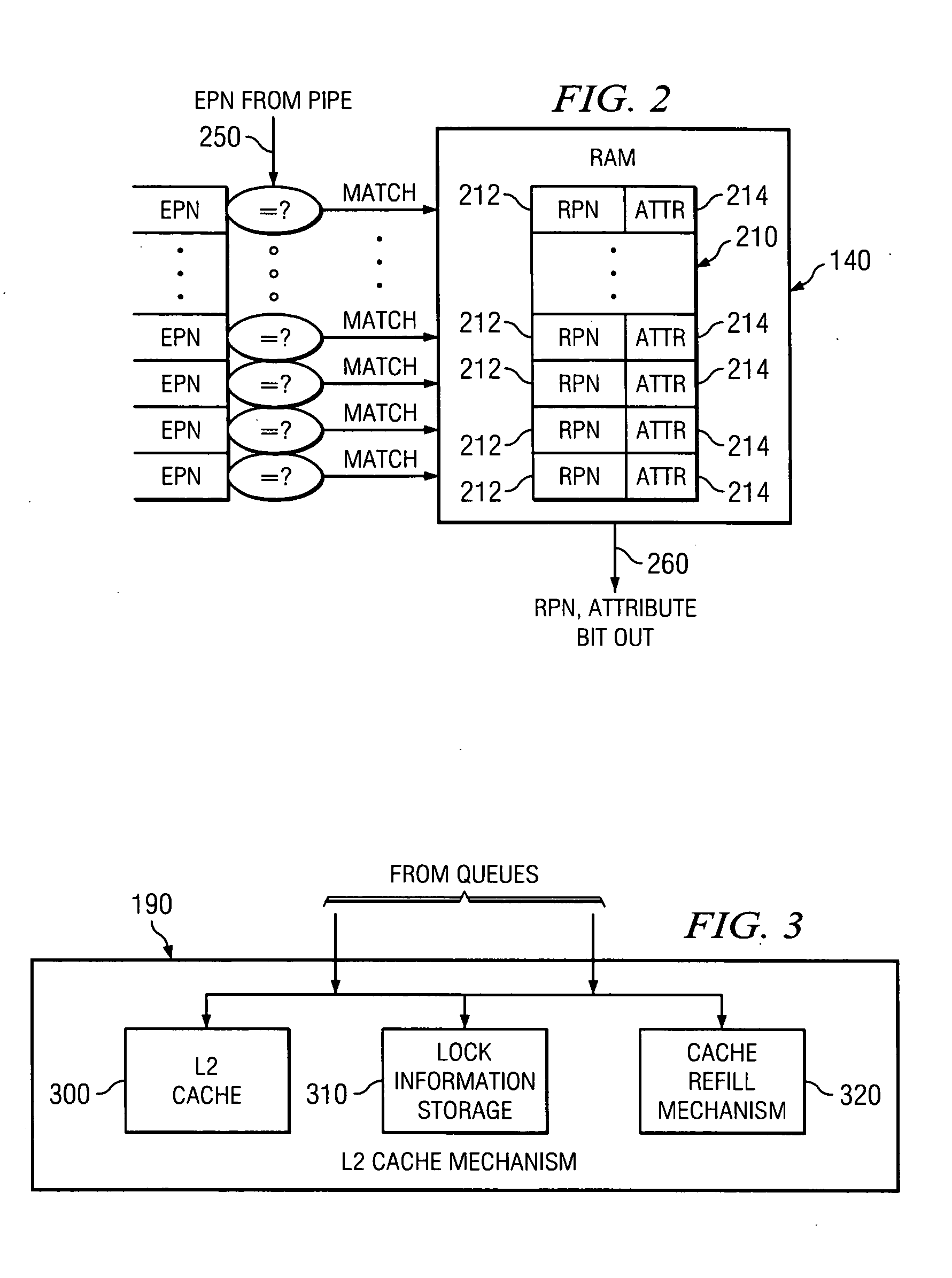
[0008] Systems and methods for the implementation of more efficient cache locking mechanisms are disclosed. These systems and methods may alleviate the need to present both a virtual address (VA) and a physical address (PA) to a cache mechanism. By eliminating the need for both of these addresses, the hardware requirements needed to implement a cache locking mechanism are eased by reducing the amount of hardware utilized to store address data in various steps of the cache pipeline. A translation table is utilized to store both the address and the locking information associated with a virtual address, and this locking information is passed to the cache along with the address of the data. The cache can then lock data based on this information. Additionally, this locking information may be used to override the replacement mechanism used with the cache, thus keeping locked data in the cache. The translation table may also store translation table lock information such that entries in the translation table are locked as well.
[0012] Embodiments of the present invention may provide the technical advantage of reducing the amount of hardware, flip-flops and / or other logic needed to implement cache locking and make implementations of cache locking substantially faster.

Problems solved by technology

Due to the relatively high cost of cache memories, however, they are typically much smaller than main memory.
Cache locking allows some or all of the contents of the cache to be locked in place, unsusceptible to the cache replacement policy implemented on the system.
Typically, however, the systems and methods utilized to lock the cache may require a large overhead.
Subsequently, however, the hardware will not replace the cache entry referenced by the second register with other data whose address is different from contents of the second register.
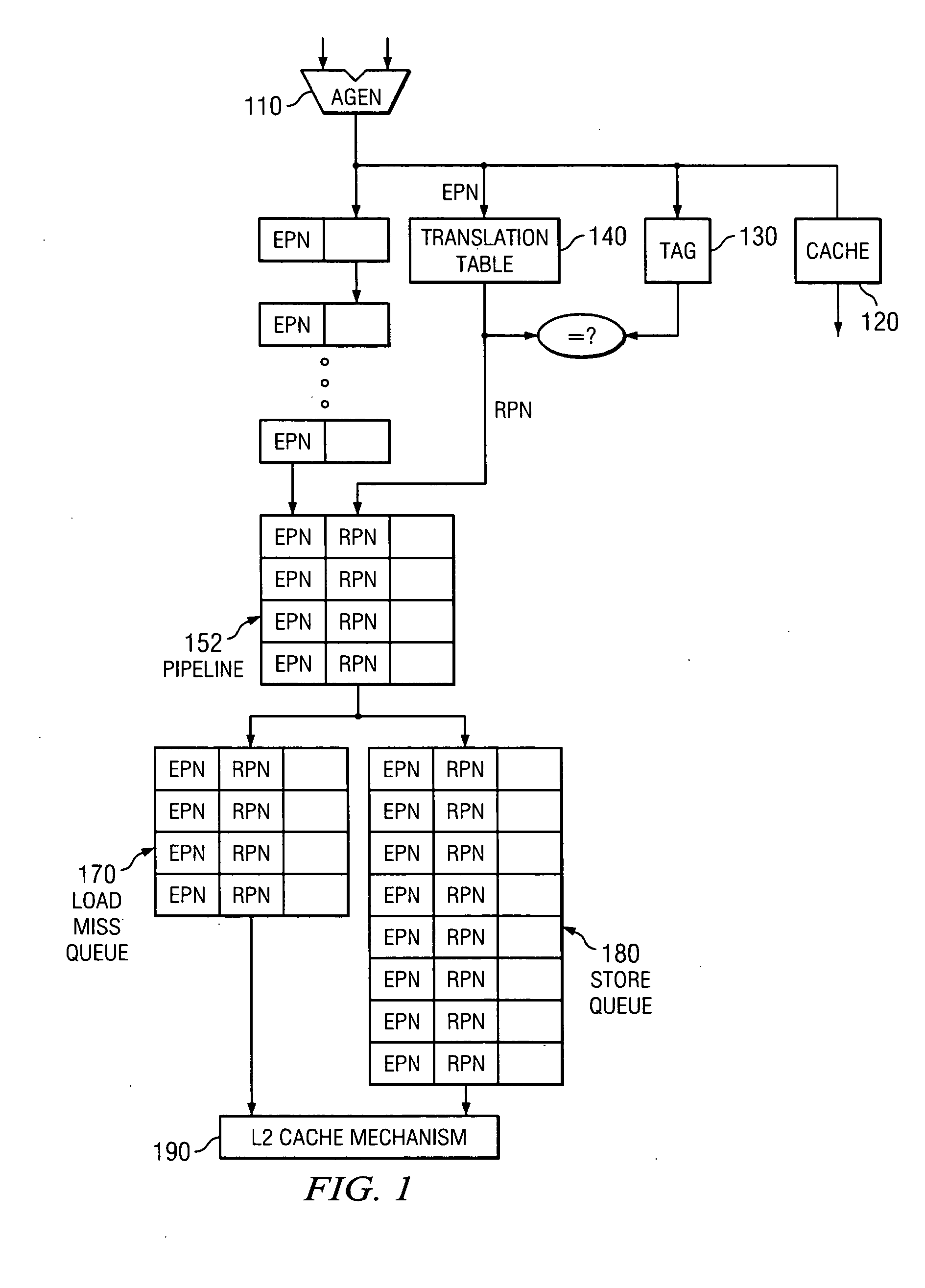
This technique may require that both the effective address and the real address (or the physical address) of data be maintained by the load and store queues of the cache which in turn imposes a heavy hardware penalty.

Method used


Image

  • Method and system for efficient cache locking mechanism
  • Method and system for efficient cache locking mechanism
  • Method and system for efficient cache locking mechanism

Examples


Embodiment Construction

[0022] The invention and the various features and advantageous details thereof are explained more fully with reference to the nonlimiting embodiments that are illustrated in the accompanying drawings and detailed in the following description. Descriptions of well known starting materials, processing techniques, components and equipment are omitted so as not to unnecessarily obscure the invention in detail. Skilled artisans should understand, however, that the detailed description and the specific examples, while disclosing preferred embodiments of the invention, are given by way of illustration only and not by way of limitation. Various substitutions, modifications, additions or rearrangements within the scope of the underlying inventive concept(s) will become apparent to those skilled in the art after reading this disclosure.

[0023] Initially, a few terms are defined or clarified to aid in an understanding of the terms as used throughout the specification. The term “translation tab...


PUM


Abstract

Systems and methods for the implementation of more efficient cache locking mechanisms are disclosed. These systems and methods may alleviate the need to present both a virtual address (VA) and a physical address (PA) to a cache mechanism. A translation table is utilized to store both the address and the locking information associated with a virtual address, and this locking information is passed to the cache along with the address of the data. The cache can then lock data based on this information. Additionally, this locking information may be used to override the replacement mechanism used with the cache, thus keeping locked data in the cache. The translation table may also store translation table lock information such that entries in the translation table are locked as well.

Description

BACKGROUND OF THE INVENTION [0001] In recent years, there has been an insatiable desire for faster computer processing data throughputs because cutting-edge computer applications are becoming more and more complex, placing ever increasing demands on microprocessing systems. The microprocessors in these systems may have very rapid cycle times and be capable of manipulating a great amount of data very quickly. The time to access the DRAM memories to which these microprocessors are coupled, however, may be considerably higher than the cycle time of the microprocessor and can vary dramatically based on the extant conditions at the time of the memory access. [0002] In order to ameliorate the bottleneck imposed by the relatively long and variable access time to memory, memory hierarchies utilizing cache memories have been implemented in conjunction with microprocessors. Cache memory augments the data storage function of main memory by providing data storage that is significantly faster th...

Claims


Application Information

Patent Timeline
IPC IPC(8): G06F12/08G06F12/14
CPCG06F12/126G06F12/1027
Inventor OSANAI, TAKEKIFERNSLER, KIMBERLY
Owner TOSHIBA ELECTRONICS DEVICES & STORAGE CORPORARTION
Why Eureka
Try Eureka