Fault tolerant control system

a control system and fault technology, applied in the field of fault tolerance control systems and methods, can solve the problems of increasing the weight and cost of computing systems, reducing the availability of systems, and always occurring systemic faults, so as to reduce the amount of hardwar

Active Publication Date: 2008-03-20
SAAB AB
View PDF6 Cites 9 Cited by
  • Summary
  • Abstract
  • Description
  • Claims
  • Application Information

AI Technical Summary

Benefits of technology

[0009] A system is provided that divides the backup system into two parts wherein randomly generated faults are detected and handles by using a more or less identical hardware which is already needed in order to guarantee the availability of the normal functions of the control system and wherein the backup system, a software program, focuses to handle systematically generated faults and thereby the amount of hardware can be reduced.
[0010] According to a first aspect, the present invention provides a fault tolerant data processing system for controlling a real time process, said system being tolerant to systematic faults in its software and comprising a data processor unit with a program memory and a data memory and input and output units where program software residing in the program memory can be executed on the data processor unit. The system comprises a normal-mode software program residing in said program memory, and a backup-mode software program also residing in said program memory arranged to perform the same or similar function of the normal mode software program but being differently implemented than the normal-mode software program, and where a trigger signal received by the data processor unit can switch execution control such that the normal-mode software program stops executing and the backup-mode software program starts executing.

Problems solved by technology

The systematic faults will always occur when certain criteria are fulfilled during the execution of a program, such as receiving certain input data.
The system switches between two programs when an error occurs in the memory of one of the programs.
The main problem with backup systems of today is that they increase the weight and the cost of the computing systems as well as reduce the availability of the system.

Method used


Image

  • Fault tolerant control system
  • Fault tolerant control system
  • Fault tolerant control system

Examples


first embodiment

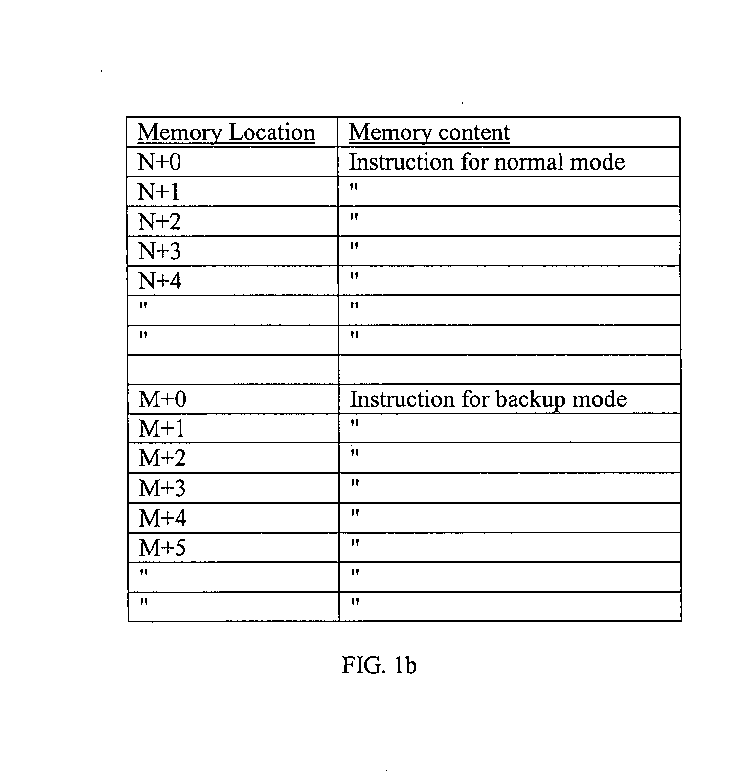
[0049] The difference between normal mode instruction and backup mode instructions in the first embodiment is that normal mode instructions have been developed in a process with a number of design goals giving high priority to high efficiency and performance and using a certain high level language and a certain low level language instruction generator when programming. The backup mode instructions have been developed in a process with a number of design goals giving high priority to simplicity and robustness and using another high level language and another low level language instruction generator when programming. In this way, a fault or a bug in the normal mode instructions causing a runtime error under certain conditions is not likely to have a counterpart in the backup mode instructions.

[0050] Thus, the backup program software may differ in the requirements from the normal program software by using different algorithms and differing in the implementation of the program by using ...

second embodiment

[0051] Referring now to FIG. 1c, a schematic illustration of the present invention, a distributed flight control system 1 of a flight vehicle is disclosed. The control system 1 comprises a number of control elements such as cockpit instruments 2, flight control computer (FCC) 3, actuator node 4, engine 5, air brakes 6 and the likes. An actuator node 4 may be adapted to control canard, elevon control surfaces or the likes of the flight vehicle. The system also receives readings from a number of sensors 7-9. These sensors are used to collect data, parameters, to provide the flight control system with input data. The sensors may be accelerometers, rate gyros, instruments that collect air data and the likes. The FCC 3, in the illustrated embodiment, comprises control laws, activation units and a backup system according to the present invention whereas other nodes of the system may not need backup systems. This may be the case when the nodes comprise rather non complex functions that can...

third embodiment

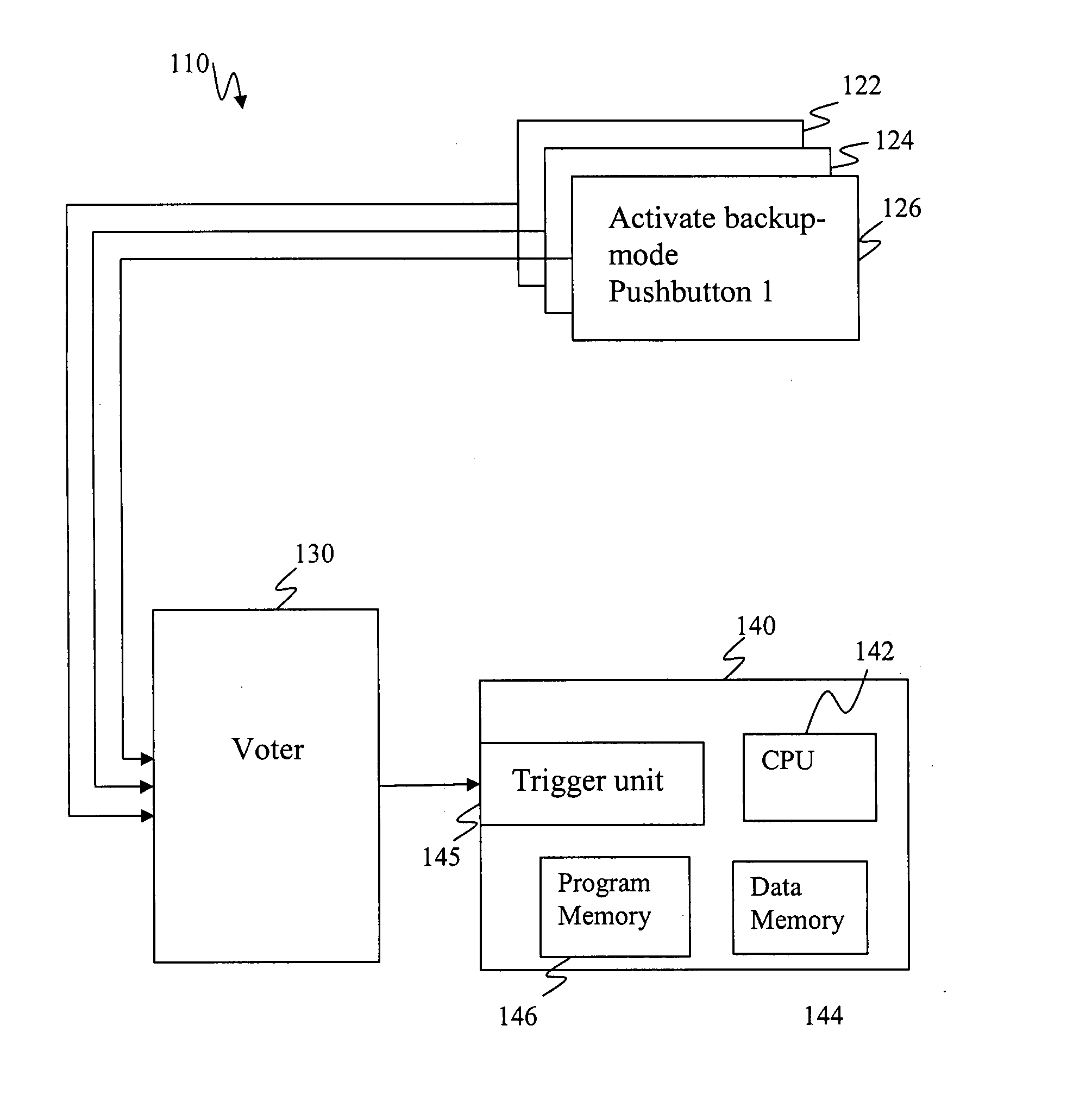
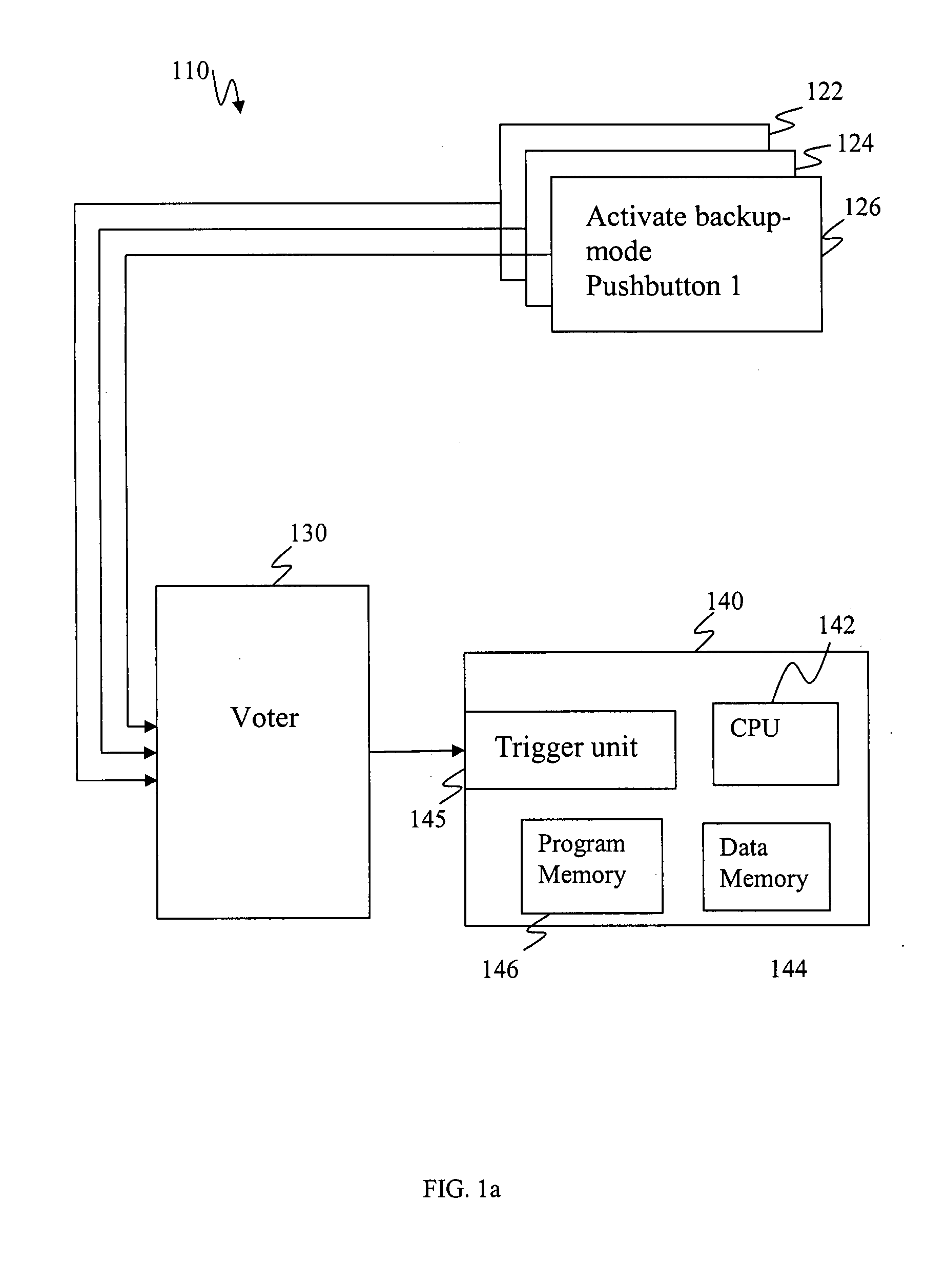
[0053] In FIG. 2 an overview of a control system 210 according to the invention is shown. In the illustrated embodiment the activation of the backup mode software program is decided based on a number of activation units, wherein the illustrated system comprises three activation units 222, 224, 226, which activation units 222, 224, 226 may be implemented in a number of other system nodes, each of these system nodes may calculate similar algorithms as the control system and compare the output of the control system to their calculation, if majority of system nodes detect a significant mismatch from the output value of the control system to the calculated value, they can activate the backup mode software program in the control system via a voter 230. The activation units may be monitoring devices that monitor the FCC in FIG. 1c. An activation unit is monitoring that an output is generated from a process within the FCC, another is a sensor that is monitoring an instrument affected by sai...


PUM


Abstract

A fault tolerant data processing system for controlling a real time process. The system is tolerant to systematic faults in its software. The system includes a data processor unit with a program memory and a data memory and input and output units where program software residing in the program memory can be executed on the data processor unit. The system includes a normal-mode software program residing in the program memory, and a backup-mode software program also residing in the program memory arranged to perform the same or similar function of the normal mode software program but being differently implemented than the normal-mode software program, and where a trigger signal received by the data processor unit can switch execution control such that the normal-mode software program stops executing and the backup-mode software program starts executing.

Description

CROSS-REFERENCE TO RELATED APPLICATION This application claims priority to European patent application number 06114052.9 filed 16 May 2006. THE FIELD OF THE INVENTION [0001] The present invention relates to fault tolerant control systems and method for activating backup functions and, especially, control systems and methods in a flight vehicle wherein a backup system is divided to detect / handle faults generated by different causes. BACKGROUND OF THE INVENTION [0002] Today's aircraft are provided with a number of control systems, these control systems requires an independent backup system in order to secure that no single faults (systematically or randomly occurring faults) can cause a system failure. Traditional backup system often tries to solve two problems at the same time, i.e. both to take care of the systematic faults, and to take care of randomly occurring faults, whereby the system can operate independently if the fault is a randomly generated fault or a systematically gene...

Claims


Application Information

Patent Timeline
Patent Type & Authority Applications(United States)
IPC IPC(8): G06F11/07
CPCG06F11/183G06F11/1641G06F11/1479G06F11/2097
Inventor JOHANSSON, RIKARDWISTED, KJELL
Owner SAAB AB
Why Eureka
Try Eureka