Method and device for sampling an image sensor

a technology for image sensors and sampling devices, applied in the direction of picture signal generators, solid-state device signal generators, television systems, etc., can solve problems such as recording pulsed light sources, and achieve the effect of reducing aliasing effects and improving signal-to-noise ratio

Active Publication Date: 2019-09-10
ROBERT BOSCH GMBH
View PDF8 Cites 1 Cited by
  • Summary
  • Abstract
  • Description
  • Claims
  • Application Information

AI Technical Summary

Benefits of technology

[0018]Here, adjacent sensor elements are for example equipped with filters so that these sensor elements produce signals that are assigned to different light properties (e.g. color through different wavelength ranges) or so that a different state of polarization can be recognized. In the step of reading out, sensor elements are sampled that are configured to detect light in a same wavelength range, for example that are configured to recognize blue, green, red, or white light. A point of acquisition of the image sensor can be understood as a region of the image sensor to which the image information is assigned. For example, this point of acquisition can be situated within a region of the image sensor that is situated through an (imaginary) connection of the read-out sensor elements. In this way, an averaging, interpolation, or weighting can be achieved of the individual read-out or buffered sensor signals, in order in this way to enable a reconstruction at a point on the image sensor. The configuration on a lattice having a triangular elementary cell is particularly advantageous if four different image sensor types are used, for example red, green, blue, and white, or any other combination of four different image sensor types (possible image sensor types: R, G, B, yellow, magenta, white, log scale white, polarization directions, etc.)
[0027]The approach presented here thus creates a device that is configured to carry out, control, or realize the steps of a variant of a method presented here in corresponding devices. Through this variant embodiment of the present invention in the form of a device as well, the object of the present invention can be achieved quickly and efficiently.

Problems solved by technology

In the temporal signal, aliasing effects show up as rolling shutter effects (a straight object is imaged as curved), effects such as the “wagon wheel effect” (from a particular speed, a wheel appears to rotate backwards), and problems in the recording of pulsed light sources (LED traffic signals, rear lights of vehicles).

Method used


Image

  • Method and device for sampling an image sensor
  • Method and device for sampling an image sensor
  • Method and device for sampling an image sensor

Examples


Embodiment Construction

[0050]In the following description of advantageous exemplary embodiments of the present invention, identical or similar reference characters are used for elements shown in the various Figures having similar function, and repeated description of these elements is omitted.

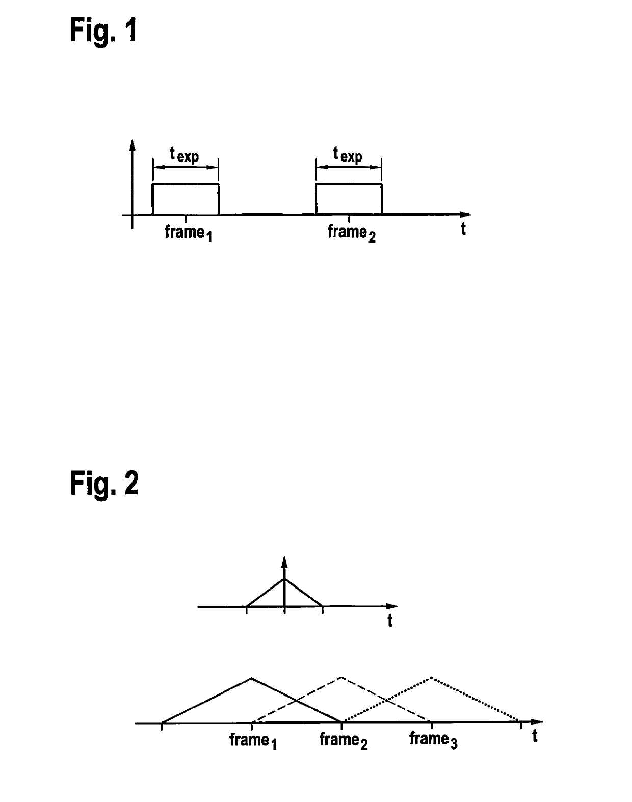
[0051]For the understanding of the approach proposed here, first the functioning of image sensors is again discussed. The current functioning of image sensors produces a relatively short exposure time compared to the resulting frame rate. The exposure time acts as a low-pass filter that can be regarded in idealized form as a rectangle in the time domain. In the frequency space, the rectangular low-pass filter having broad texp is represented as an si function:

[0052]⁢rect⁡(ttexp.)⁢⁢si⁡(π⁢⁢f⁢⁢texp.)(1)

[0053]The first zero crossing of the si curve is at:

[0054]π⁢⁢f⁢⁢texp.=π(2)fcutoff=1texp.(3)

[0055]and is at the same time a standard approximation of the cutoff frequency of the low-pass filter. If we compare standard expo...


PUM


Abstract

A method for sampling an image sensor, the image sensor having a lattice structure having a plurality of triangular sensor elements. In the lattice structure, sensor elements situated adjacent to one another are configured to detect light having respectively different light properties. The method includes a step of reading out the image sensor by sampling a plurality of sensor elements of the lattice structure that are configured to detect light in a same first wavelength range, one sensor signal being read out per sensor element in the step of reading out. In addition, the method includes a step of buffering the read-out sensor signals and a step of producing an item of image information assigned to a point of acquisition of the image sensor, using the buffered sensor signals.

Description

RELATED APPLICATION INFORMATION[0001]The present application claims priority to and the benefit of German patent application no. 10 2016 212 791.8, which was filed in Germany on Jul. 13, 2016, and German patent application no. 10 2016 216 985.8, which was filed in Germany on Sep. 7, 2016, the disclosures of both of which are incorporated herein by reference.FIELD OF THE INVENTION[0002]The present invention relates to a device and a method of the type indicated herein. The subject matter of the present invention is also a computer program.BACKGROUND INFORMATION[0003]Modern image sensors standardly function according to the following configuration:[0004]1. An optical mechanism produces a light image on a flat sensor (also called an image sensor or imager).[0005]2. The image sensor samples this image spatially and temporally.[0006]3. The temporal sampling is determined by the frame rate.[0007]Here, the standard camera components fulfill the following functions:[0008]The optical mechani...

Claims


Application Information

Patent Timeline
Patent Type & Authority Patents(United States)
IPC IPC(8): H04N5/378H04N5/357H04N5/369H04N5/3745H04N9/04
CPCH04N5/378H04N5/3575H04N9/045H04N5/37452H04N5/3696H04N25/616H04N25/633H04N25/702H04N25/771H04N25/134H04N25/75
Inventor GEESE, MARCSEGER, ULRICH
Owner ROBERT BOSCH GMBH
Why Eureka
Try Eureka