
Diagnosis system for vehicular DC charging relay

a technology of diagnostic system and relay, which is applied in the direction of battery/fuel cell control arrangement, electric devices, instruments, etc., can solve problems such as accidents, and achieve the effect of reducing cost and high diagnostic efficiency

Active Publication Date: 2019-09-17
NIO CO LTD
View PDF2 Cites 1 Cited by
  • Summary
  • Abstract
  • Description
  • Claims
  • Application Information

AI Technical Summary

Benefits of technology

The present invention provides a diagnosis system for vehicular DC charging relay with high efficiency and low cost. The system can accurately and quickly diagnose the operating state of the DC charging relay, right after the vehicle's charging port is disconnected from the external charger. This allows for quick and affordable maintenance and repair of the auseable parts.

Problems solved by technology

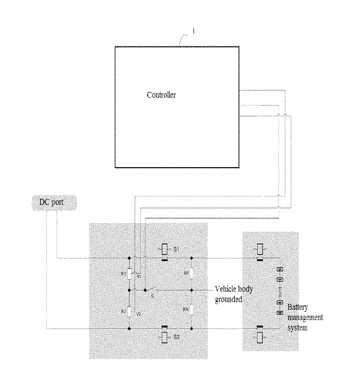
In a prior technical solution, typically two high voltage relays (e.g. high voltage relay S1 and S2 in FIG. 1) are added into a high voltage bus loop which is used for DC charging, thus, in the case of non-DC charging, the two high voltage relays is disconnected by a controller, to ensure that the high voltage electricity will not be exposed to the outside and result in accidents.
However, the above prior technical solution has the following problems: due to the physical / mechanical features of the relay, the contacts of the two high voltage relays are likely to adhere (i.e., loose efficacy since keep staying in a closed state for a long time) in the course of operation, in this case, the high voltage electricity on an internal high voltage circuit may be exposed to the outside, thereby potential accidents may be caused.

Method used


Image

  • Diagnosis system for vehicular DC charging relay

Examples


Embodiment Construction

[0023]FIG. 1 is a schematic structure diagram of the diagnosis system for vehicular DC charging relay according to the invention. As showed in FIG. 1, the diagnosis system for vehicular DC charging relay disclosed in the invention comprises: a controller 1, two resistor clusters R1 and R2, and a switch S, wherein, the two resistor clusters R1 and R2 are bridging in a serially connected way in between DC charging high voltage cables of the vehicle, a first terminal of the resistor cluster R1 is electrically connected to one side of the DC charging high voltage cable of the vehicle and a first terminal of the resistor cluster R2 is electrically connected to the other side of the DC charging high voltage cable of the vehicle, a second terminal of the resistor cluster R1, a second terminal of the resistor cluster R2, and a first terminal of the switch S are electrically connected, and a second terminal of the switch S is in connection with a ground of the vehicle body, and wherein, the ...


PUM


Abstract

The present invention provides a diagnosis system for vehicular DC charging relay, the system comprises a controller, two resistor clusters R1 and R2, and a switch S, wherein, two resistor clusters R1 and R2 are bridging in a serially connected way in between the DC charging high voltage cables of the vehicle, the resistor cluster R1 consists of two serially connected sub-resistors, and the controller is able to measure a voltage V1 at a common terminal of the two serially connected sub-resistors via a first voltage detection port, the resistor cluster R2 consists of two serially connected sub-resistors, and the controller is able to measure a voltage V2 at a common terminal of the two serially connected sub-resistors via a second voltage detection port, the controller is able to execute a diagnosis operation, and the diagnosis operation is based on the measurements of the voltages V1 and V2.

Description

CROSS-REFERENCE TO RELATED APPLICATIONS[0001]This application claims the benefit of China Patent Application No. 201710075641.7 filed Feb. 13, 2017, the entire contents of which are incorporated herein by reference.FIELD OF INVENTION[0002]The present invention relates to diagnosis systems, and more particularly, to a diagnosis system for vehicular DC charging relay.BACKGROUND[0003]At present, with the increasing development and popularization of electric control systems (e.g. an electric control system in a pure electric / hybrid vehicle), charging a power battery pack of a vehicle (e.g. a pure electric / hybrid vehicle) using DC current via a charging station or a charging pile is becoming more and more important.[0004]In a prior technical solution, typically two high voltage relays (e.g. high voltage relay S1 and S2 in FIG. 1) are added into a high voltage bus loop which is used for DC charging, thus, in the case of non-DC charging, the two high voltage relays is disconnected by a con...

Claims


Application Information

Patent Timeline
Patent Type & Authority Patents(United States)
IPC IPC(8): G01R31/327B60L3/00B60L50/50B60L53/30B60L58/10G01R31/00
CPCB60L50/50B60L3/0023B60L58/10G01R31/3275B60L53/30G01R31/3278G01R31/3274Y02T10/7005G01R31/006B60L50/60Y02T10/70Y02T10/7072Y02T90/12
Inventor ZHOU, YI
Owner NIO CO LTD
Learn More