Dynamic magnetic resonance imaging with variable contrast

a magnetic resonance imaging and contrast technology, applied in the field of dynamic magnetic resonance imaging with variable contrast, can solve the problems of limiting efficiency, increasing complexity, and measuring duration, and achieve the effect of reducing the number of raw data points actually recorded and reducing the echo tim

Active Publication Date: 2019-09-24
SIEMENS HEALTHCARE GMBH
View PDF19 Cites 0 Cited by
  • Summary
  • Abstract
  • Description
  • Claims
  • Application Information

AI Technical Summary

Benefits of technology

[0009]Through the use of the MR images in the second cycle, in which the magnetization is close to the state of equilibrium, the movement information can be reliably determined, since the contrast change in this series of MR images of the second cycle is now small. It is thus possible to compute the movement information, which can be deformation information for example, reliably with the MR images in the second cycle. This movement information is then transferred to the MR images in the first cycle in which the magnetization is further away from the state of equilibrium. This means that the individual MR images in the first cycle differ more strongly in contrast. Since now, with the aid of the movement information, movement-corrected MR images for the various movement phases of the cyclic movement are computed, MR images are obtained for the various movement phases of the cyclic movement and for various contrasts. Furthermore, it is no longer necessary to define before image recording which contrast or which phase of the cyclic movement is of interest, since this choice can be determined retrospectively after the recording of the MR images since MR image series have been computed for various contrasts.
[0019]For a recording of many MR images within one heart cycle it is possible to record the MR images with the aid of acceleration methods, for example compressed-sensing technology. As is known, this technique continues to reduce the echo time, in that certain conditions of the recorded MR data are exploited in order to reduce the number of raw data points actually recorded.

Problems solved by technology

The first option limits the measurement duration and the second option limits efficiency and increases complexity.

Method used


Image

  • Dynamic magnetic resonance imaging with variable contrast
  • Dynamic magnetic resonance imaging with variable contrast
  • Dynamic magnetic resonance imaging with variable contrast

Examples


Embodiment Construction

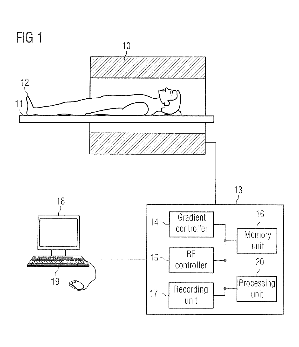
[0027]FIG. 1 shows a schematic of a magnetic resonance apparatus, with which, in accordance with the invention, MR images of an examination object, such as an organ which executes a cyclic movement, can be created with different contrasts. The magnetic resonance apparatus has a magnet 10 for creating a polarization field BO, wherein a person being examined 12, located on a bed 11, is moved into the center of the magnet, in order for locally-encoded magnetic resonance signals from an examination object to be recorded there. By applying radio-frequency pulses and switching of magnetic field gradients, the magnetization created by the polarization field B0 can be deflected from the state of equilibrium and the magnetization produced can be detected in magnetic resonance signals with receive coils not shown in the figure. The general functions for creation of magnetic resonance signals with various imaging sequences are known to the person skilled in the art, so that no detailed explana...


PUM


Abstract

In a method for computing MR images of an examination object that performs a cyclic movement, MR signals are detected over at least two cycles of the cyclic movement. In each of these cycles, data for multiple MR images are recorded. Over these cycles, a magnetization of the examination object that influences the MR images approaches a state of equilibrium in a second of these cycles is closer to the state of equilibrium than in a first of these cycles. Movement information for various movement phases of the cyclic movement of the examination object is determined using the MR images from the second cycle, with movement information of the examination object determined for each of the various movement phases. Movement correction of the examination object is carried out in the MR images of the first cycle using the movement information determined in the second cycle.

Description

BACKGROUND OF THE INVENTION[0001]Field of the Invention[0002]The present invention relates to a method for computing MR images of an examination object which executes a cyclic movement and to an MR apparatus for this purpose.[0003]Description of the Prior Art[0004]In the acquisition of MR images of moving organs, the inherent movement of the organ, of the heart for example, must be taken into account and possibly the movement of the organ overall as a result of the movement of the surroundings. This is the case for movement of the heart or of the liver during breathing, wherein this second movement is expectedly a repetitive and almost periodic movement. A first option for the imaging of moving objects is a technique known as the single-shot technique, in which the raw data space (k-space) is read out (filled) completely after the application of an RF pulse and in which the recording of the data is fast enough to freeze the movement. The further recording option is the segmented rec...

Claims


Application Information

Patent Timeline
Patent Type & Authority Patents(United States)
IPC IPC(8): A61B5/055A61B5/00G01R33/50G01R33/563G01R33/565
CPCG01R33/56509G01R33/56325A61B5/742A61B5/0044A61B5/055G01R33/50A61B5/7214A61B2576/00
Inventor GREISER, ANDREASSCHMIDT, MICHAELASPEIER, PETERSTALDER, AURELIENZENGE, MICHAEL
Owner SIEMENS HEALTHCARE GMBH
Why Eureka
Try Eureka