Ignition device
a technology of ignition coil and ignition coil, which is applied in the direction of spark gap circuit, machine/engine, pulse technique, etc., can solve the problems of primary current keeping flowing abnormality may occur, and the signal for turning off may not be transmitted for a long time, so as to protect the primary winding of the ignition coil, the effect of lowering the forcible turn-off temperature and reliably protecting the ignition coil
- Summary
- Abstract
- Description
- Claims
- Application Information
AI Technical Summary
Benefits of technology
Problems solved by technology
Method used
Image


Examples
first embodiment
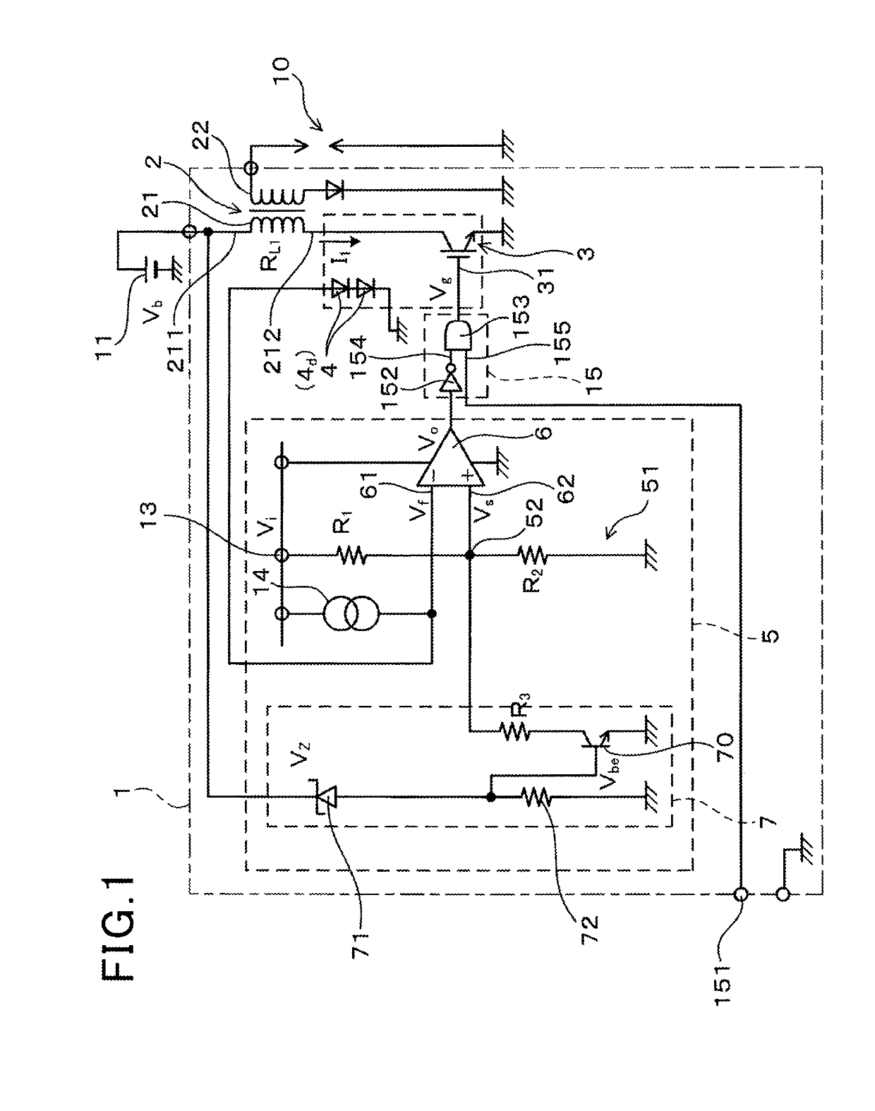
[0038]An ignition device in accordance with a first embodiment of the present invention will be described with reference to FIGS. 1-10. The ignition device of the present embodiment may be a vehicle-mounted ignition device, that is, an ignition device mounted in a vehicle. As shown in FIG. 1, an ignition device 1 of this embodiment comprises an ignition coil 2, a switching element 3, a temperature sensor 4, and a thermal cutout circuit 5. The ignition coil 2 includes a primary winding 21 and a secondary winding 22. One end 211 of the primary winding 21 is connected to a DC power supply 11. The DC power supply 11 of this embodiment is a lead storage battery. The switching element 3 is connected between the end 212 of the primary winding 21 that is opposite from the end connected with the DC power supply 11 and the ground. A spark plug 10 is connected to the secondary winding 22.
[0039]The temperature sensor 4 is provided to measure the temperature of the switching element 3.
[0040]The ...
second embodiment
[0085]This embodiment is an example in which the number of reference voltage shift circuits 7 is changed. As shown in FIG. 11, the ignition device 1 of this embodiment includes a plurality of reference voltage shift circuits 7 (7a-7c). Similarly to the first embodiment, each of the reference voltage shift circuits 7 includes a Zener diode 71, a resistor 72, a third resistor R3 (R3a-R3c), and a transistor 70.
[0086]The breakdown voltage Vz of each Zener diode 71 is different from one another. The breakdown voltage Vza of the first zener diode 71a is the highest and the breakdown voltage Vzc of the third zener diode 71c is the lowest. The breakdown voltage Vzb of the second Zener diode has a value between Vza and Vzc. As with the first embodiment, these breakdown voltages Vz are set to values lower than the power supply voltage Vb.
[0087]When the power supply voltage Vb decreases, first, the first Zener diode 71a stops to break down. Thus, the transistor 70a of the first reference volta...
third embodiment
[0091]This embodiment is an example in which the configuration of the reference voltage shift circuit 7 is changed. As shown in FIG. 14, the reference voltage shift circuit 7 of this embodiment includes a subtraction circuit 79 and the voltage dividing circuit 77. The voltage dividing circuit 77 includes two resistors Re and Rf connected in series with each other. The power supply voltage V b is applied to the voltage dividing circuit 77. The voltage dividing circuit 77 provides a divided voltage value Vb′ of the power supply voltage Vb. The divided voltage value Vb′ can be expressed by the following expression.
Vb′=VbRf / (Re+Rf)
[0092]Further, the subtraction circuit 79 includes an operational amplifier 78 and a plurality of resistors Ra-Rd. A non-inverting input terminal 781 of the operational amplifier 78 is connected to the constant voltage circuit 13. An inverting input terminal 782 of the operational amplifier 78 is connected to the voltage dividing circuit 77. The output of the ...
PUM
| Property | Measurement | Unit |
|---|---|---|
| voltage Vb | aaaaa | aaaaa |
| turn-off | aaaaa | aaaaa |
| turn-off | aaaaa | aaaaa |
Abstract
Description
Claims
Application Information