
Crystal resonator

a crystal resonator and resonator technology, applied in the direction of impedence networks, electrical devices, etc., can solve the problems of sudden frequency change, change in crystal impedance (ci), and difficulty in reducing unwanted responses

Active Publication Date: 2019-09-24
NIHON DEMPA KOGYO CO LTD
View PDF18 Cites 2 Cited by
  • Summary
  • Abstract
  • Description
  • Claims
  • Application Information

AI Technical Summary

Benefits of technology

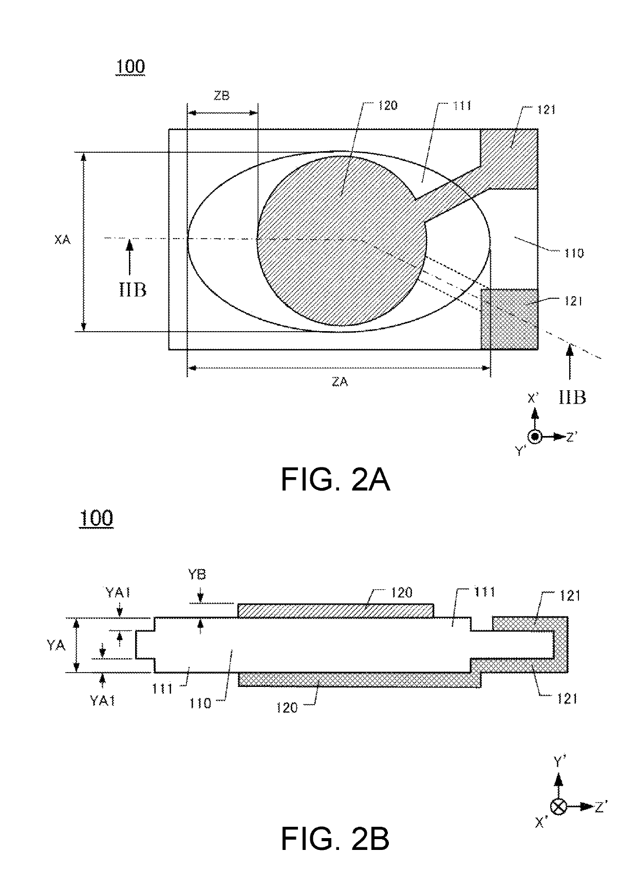
[0028]Conventionally, while the crystal element has been formed into the square plate shape in accordance with downsizing of the crystal resonator, to provide the excitation electrode with a large area in order to achieve a good electric constant, the excitation electrode has been formed into the square shape. However, the square excitation electrode is likely to cause a coupling of an unwanted response in a flexure mode with a reflected wave from an end surface of the crystal element. This has caused a variation of and an increase in CI value. In contrast to this, a circular excitation electrode can reduce the reflected wave from the end surface of the crystal element and can prevent the coupling, thereby ensuring preventing the variation of and the increase in CI value.

Problems solved by technology

However, the doubly-rotated crystal resonator as disclosed in JP-A-5-243890 has the following problems.
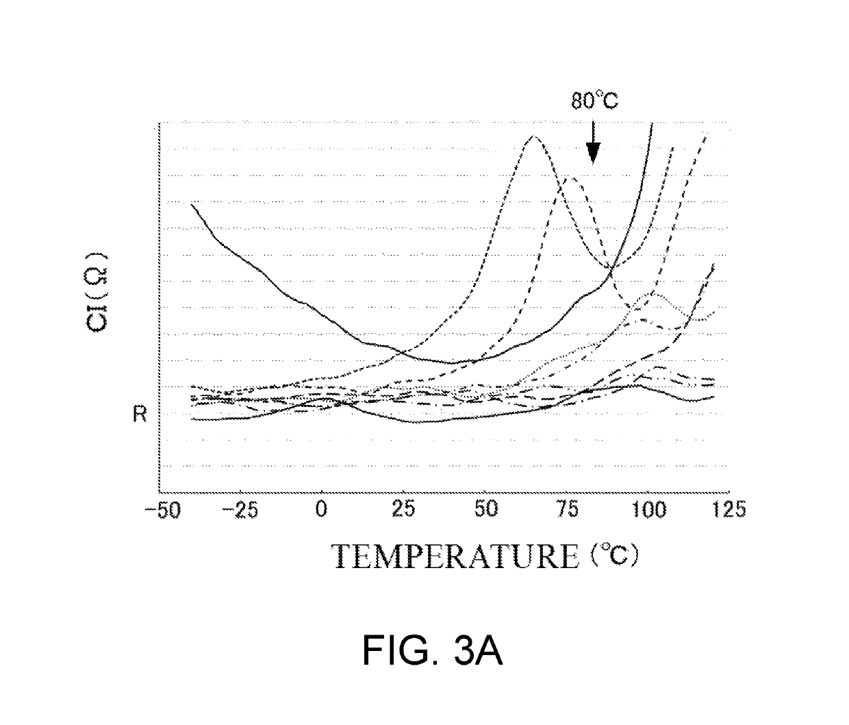
This is likely to cause a sudden frequency change and a change in crystal impedance (CI) due to a temperature change.
Since the doubly-rotated crystal resonator and the AT-cut crystal resonator have modes of vibration different from one another, it is difficult to reduce the unwanted response with the use of the technique of the AT-cut crystal resonator for the doubly-rotated crystal resonator as it is.

Method used


Image

  • Crystal resonator
  • Crystal resonator
  • Crystal resonator

Examples


first embodiment

[0023][Configuration of Crystal Resonator 100 ]

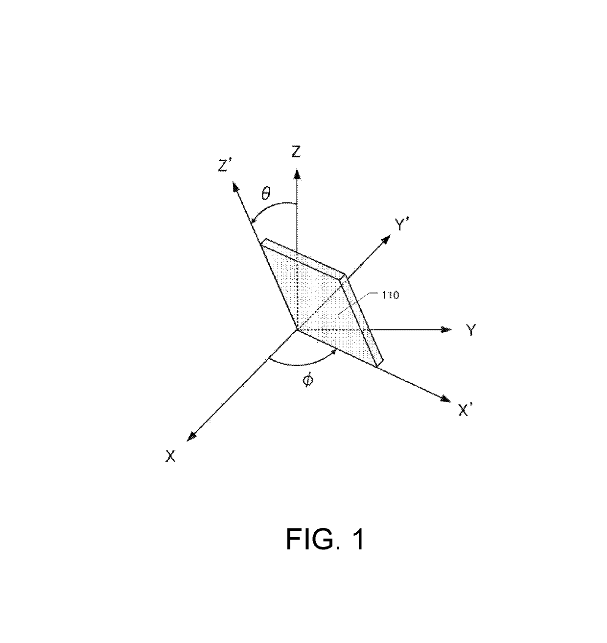
[0024]FIG. 1 is an explanatory drawing of a doubly-rotated cut crystal element 110. FIG. 1 denotes crystallographic axes for a crystal as an X-axis, a Y-axis, and a Z-axis. The doubly-rotated cut crystal element 110 is formed by cutting the crystal parallel to an X′-axis, an axis of rotating the X-axis as the crystallographic axis of the crystal around the Z-axis by ϕ degrees as the crystallographic axis of the crystal and a Z′-axis, an axis of rotating the Z-axis around the X′-axis by θ degrees. Therefore, the doubly-rotated cut crystal element 110 is formed such that the X′-Z′ surface becomes a principal surface. FIG. 1 shows a Y′-axis perpendicular to the X′-axis and the Z′-axis.

[0025]As the doubly-rotated cut crystal element illustrated in FIG. 1, for example, there has been known an SC-cut crystal element with ϕ of approximately 22 degrees and θ of approximately 34 degrees, an IT-cut crystal element with ϕ of approximately 19 degre...

second embodiment

[0045][Second Embodiment]

[0046]The crystal element can be formed into various shapes. The following describes modifications of the crystal element.

[0047][Configurations of Crystal Resonator 200a and Crystal Resonator 200b]

[0048]FIG. 5A is a plan view of the crystal resonator 200a. The crystal resonator 200a includes a crystal element 210, the excitation electrodes 120, and extraction electrodes 221a. The crystal element 210 has square principal surfaces, and the mesa portions 111 are formed on the crystal element 210. The excitation electrodes 120 are formed on the mesa portions 111 on both principal surfaces of the crystal element 210. The extraction electrodes 221a are extracted from the respective excitation electrodes 120. While the crystal element 110 (see FIG. 2A) is formed into the rectangular shape, arranging the shape of the square crystal element 210, which has the short side length identical to the long side length, is also easy and the production cost can be reduced low,...

third embodiment

[0062][Third Embodiment]

[0063]The formation of an inclined portion whose surface is inclined at a peripheral area of an excitation electrode and a peripheral area of a mesa portion can also reduce the flexure vibration. The following describes a crystal resonator with the inclined portion.

[0064][Configuration of Crystal Resonator 500]

[0065]FIG. 8A is a plan view of the crystal resonator 500. The crystal resonator 500 includes a crystal element 510, which includes a mesa portion 511, excitation electrodes 520, and the extraction electrodes 121. The excitation electrode 520 is formed to have a circular shape identical to the excitation electrode 120 illustrated in FIG. 2A. The excitation electrode 520 includes a center portion 520a with constant thickness and an inclined portion 520b. The inclined portion 520b is formed at a peripheral area of the center portion 520a and has a thickness decreasing from the inner peripheral side to the outer peripheral side. FIG. 8A indicates the insid...


PUM


Abstract

A crystal resonator includes a crystal element and excitation electrodes. The crystal element has a pair of principal surfaces parallel to an X′-axis and a Z′-axis. The X′-axis is an axis of rotating an X-axis as a crystallographic axis of a crystal in a range of 15 degrees to 25 degrees around a Z-axis as a crystallographic axis of the crystal. The Z′-axis is an axis of rotating the Z-axis in a range of 33 degrees to 35 degrees around the X′-axis. The excitation electrodes are formed on the respective principal surfaces of the crystal element. Elliptical mesa portions or elliptical inverted mesa portions are formed on the respective principal surfaces. The mesa portions project from outer peripheries of the principal surfaces. The inverted mesa portions are depressed from the outer peripheries of the principal surfaces.

Description

CROSS-REFERENCE TO RELATED APPLICATIONS[0001]This application is based on and claims priority under 35 U.S.C. § 119 to Japanese Patent Application No. 2016-080528, filed on Apr. 13, 2016, the entire content of which is incorporated herein by reference.TECHNICAL FIELD[0002]This disclosure relates to a crystal resonator where a doubly-rotated cut crystal element is used.DESCRIPTION OF THE RELATED ART[0003]There has been known a doubly-rotated crystal resonator that uses a doubly-rotated cut crystal element. The doubly-rotated cut crystal element is formed by cutting a crystal parallel to an X′-axis, an axis of rotating an X-axis as a crystallographic axis of the crystal by ϕ degrees around a Z-axis as a crystallographic axis and a Z′-axis, an axis of rotating the Z-axis around the X′-axis by θ degrees. Japanese Unexamined Patent Application Publication No. 5-243890 describes an SC-cut crystal resonator with, for example, ϕ of approximately 22 degrees and θ of approximately 34 degrees....

Claims


Application Information

Patent Timeline
Patent Type & Authority Patents(United States)
IPC IPC(8): H03H9/17H03H9/02H03H3/04
CPCH03H3/04H03H9/02015H03H9/17H03H2003/0407H03H9/10H03H9/19
Inventor OBARA, SHIGERUSATO, TETSUYANAKAHARA, MASAAKISHIBAZAKI, TOMONORIOI, YUKINISHIMURA, YUYA
Owner NIHON DEMPA KOGYO CO LTD
Learn More