Magnetic tape having characterized magnetic layer and magnetic tape device
a magnetic layer and magnetic tape technology, applied in the direction of magnetic tape recording, maintaining head carrier alignment, instruments, etc., can solve the problems of difficult to ensure the correct follow-up of data by the magnetic head, errors may easily occur at the time of recording and/or reproduction, etc., to achieve improved head positioning accuracy and high surface smoothness
Active Publication Date: 2019-10-01
FUJIFILM CORP
View PDF332 Cites 34 Cited by
- Summary
- Abstract
- Description
- Claims
- Application Information
AI Technical Summary
Benefits of technology
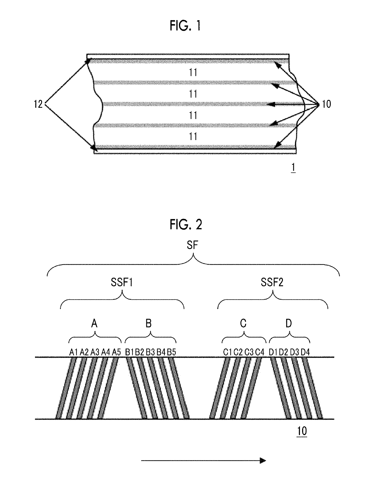
[0007]First, a servo head reads a servo signal formed in a magnetic layer. A position of a magnetic head of the magnetic tape in a width direction is controlled in accordance with the read servo signal. Accordingly, when running the magnetic tape in the magnetic tape device for recording and / or reproducing a magnetic signal (information), it is possible to increase an accuracy of the position of the magnetic head following the data track, even when the position of the magnetic tape is changed in the width direction with respect to the magnetic head. By doing so, it is possible to properly record information on the magnetic tape and / or properly reproduce information recorded on the magnetic tape.
[0009]Meanwhile, in recent years, high surface smoothness of the magnetic layer of the magnetic tape has been required. This is because the surface smoothness of the magnetic layer causes improvement of electromagnetic conversion properties. However, in the intensive studies of the inventors, it was clear that, when the high surface smoothness of the magnetic layer of the magnetic tape was increased, a phenomenon which was not known in the related art occurred, in which an accuracy of the position of the magnetic head following the data track in the timing-based servo system (hereinafter, referred to as a “head positioning accuracy”) is decreased.
[0010]Therefore, an object of the invention is to satisfy both of improvement of surface smoothness of the magnetic layer of the magnetic tape and improvement of the head positioning accuracy of the timing-based servo system.
[0025]According to one aspect of the invention, it is possible to provide a magnetic tape which has a timing-based servo pattern in a magnetic layer having high surface smoothness and has an improved head positioning accuracy of a timing-based servo system, and a magnetic tape device which records and / or reproduces a magnetic signal to the magnetic tape.
Problems solved by technology
However, when the width of the data track is narrowed and the recording and / or reproduction of magnetic signals is performed by allowing the running of the magnetic tape in a magnetic tape device (normally referred to as a “drive”), it is difficult that a magnetic head properly follows the data tracks in accordance with the position change of the magnetic tape in the width direction, and errors may easily occur at the time of recording and / or reproduction.
Method used
View moreImage
Smart ImageViewing Examples

Examples
examples
[0139]Hereinafter, the invention will be described with reference to examples. However, the invention is not limited to aspects shown in the examples. “Parts” and “%” in the following description mean “parts by mass” and “mass %”, unless otherwise noted.
Magnetic Tape Manufacturing Examples
Login to View More PUM
| Property | Measurement | Unit |
|---|---|---|
| surface roughness Ra | aaaaa | aaaaa |
| photoelectron take-off angle | aaaaa | aaaaa |
| surface roughness Ra | aaaaa | aaaaa |
Abstract
A magnetic tape includes a non-magnetic layer including non-magnetic powder and a binder on a non-magnetic support; and a magnetic layer including ferromagnetic powder and a binder on the non-magnetic layer. The magnetic layer includes a timing-based servo pattern. The center line average surface roughness Ra measured regarding the surface of the magnetic layer is less than or equal to 1.8 nm. One or more components selected from a fatty acid and a fatty acid amide are included in at least the magnetic layer, and the C—H derived C concentration calculated from the C—H peak area ratio of C1s spectra obtained by X-ray photoelectron spectroscopic analysis performed on the surface of the magnetic layer at a photoelectron take-off angle of 10 degrees is greater than or equal to 45 atom %.
Description
CROSS-REFERENCE TO RELATED APPLICATIONS[0001]This application claims priority under 35 U.S.C 119 to Japanese Patent Application No. 2016-116261 filed on Jun. 10, 2016. The above application is hereby expressly incorporated by reference, in its entirety.BACKGROUND OF INVENTION1. Field of the Invention[0002]The present invention relates to a magnetic tape and a magnetic tape device.2. Description of the Related Art[0003]Magnetic recording media are divided into tape-shaped magnetic recording media and disk-shaped magnetic recording media, and tape-shaped magnetic recording media, that is, magnetic tapes are mainly used for data storage such as data back-up or archive. The recording of information into magnetic tape is normally performed by recording a magnetic signal on a data band of the magnetic tape. Accordingly, data tracks are formed in the data band.[0004]An increase in recording capacity (high capacity) of the magnetic tape is required in accordance with a great increase in inf...
Claims
Login to View More Application Information
Patent Timeline
 Patent Type & Authority Patents(United States)
IPC IPC(8): G11B5/71G11B5/78G11B5/008G11B5/584
CPCG11B5/71G11B5/78G11B5/584G11B5/00813G11B5/70
Inventor KASADA, NORIHITOKANEKO, TETSUYAOZAWA, EIKI
Owner FUJIFILM CORP
Features
- R&D
- Intellectual Property
- Life Sciences
- Materials
- Tech Scout
- Unparalleled Data Quality
- Higher Quality Content
- 60% Fewer Hallucinations
Learn More Browse by: Latest US Patents, China's latest patents, Technical Efficacy Thesaurus, Application Domain, Technology Topic, Popular Technical Reports.
© 2025 PatSnap. All rights reserved.Legal|Privacy policy|Modern Slavery Act Transparency Statement|Sitemap|About US| Contact US: help@patsnap.com