Ink jet driving apparatus and ink jet driving method

a driving apparatus and ink jet technology, applied in the direction of printing, inking apparatus, etc., can solve the problems of degrading ink ejection properties and ejection speed, and achieve the effects of avoiding degradation of ejection properties, increasing the possibility of successfully removing ink, and increasing viscosity

a driving apparatus and ink jet technology, applied in the direction of printing, inking apparatus, etc., can solve the problems of degrading ink ejection properties and ejection speed, and achieve the effects of avoiding degradation of ejection properties, increasing the possibility of successfully removing ink, and increasing viscosity

US10434773B2Active Publication Date: 2019-10-08KONICA MINOLTA INC

Image

  • Ink jet driving apparatus and ink jet driving method
  • Ink jet driving apparatus and ink jet driving method
  • Ink jet driving apparatus and ink jet driving method

Examples


Embodiment Construction

[0037]Hereinafter, one or more embodiments of the present invention will be described with reference to the drawings. However, the scope of the invention is not limited to the disclosed embodiments.

[0038]An embodiment of the present invention will be described below with reference to the accompanying drawings. Herein, when a numerical value range is indicated as A to B, the lower limit value A and the upper limit value B are both included in the numerical value range.

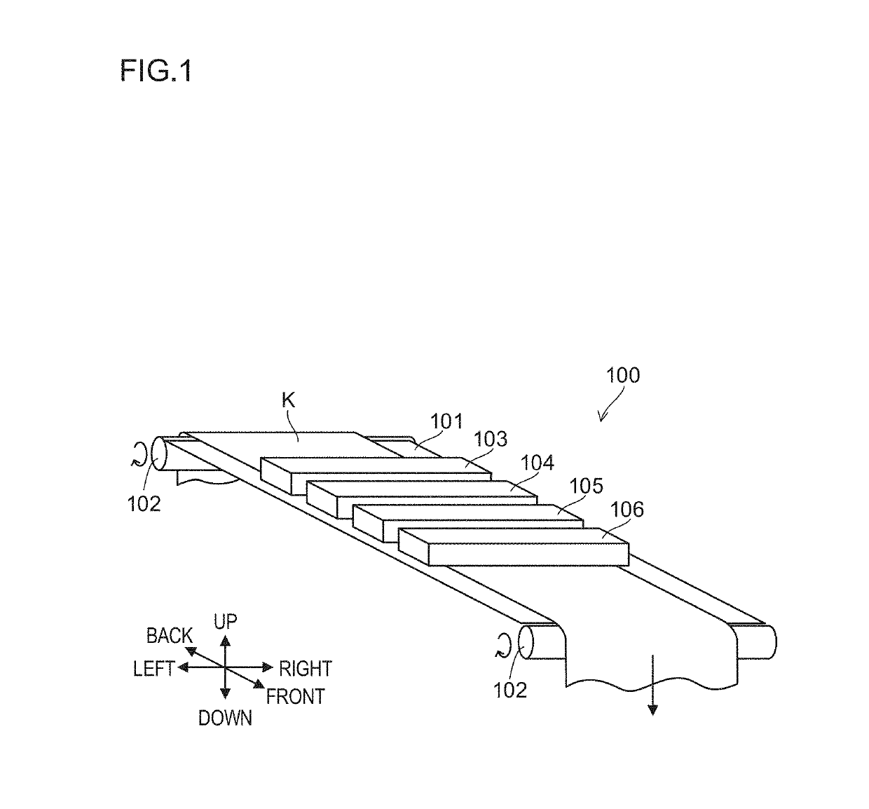
[0039]The following description deals with an embodiment, as an example, that employs a one-pass drawing method which draws images with a configuration using a line head (only by conveyance of a recording medium), but alternatively, another drawing method, such as a method using a scanning method or a drum method, may be adopted.

[0040]In the following description, a conveyance direction of a recording medium K is a front-back direction, a direction orthogonal to the conveyance direction on a conveying surface of the rec...


PUM


Abstract

When a diameter of a hole at an exit of a nozzle is expressed as D (μm) and a distance between a position in a circulation flow path part on a side thereof closest to the exit and the exit is expressed as N (μm) in an ink jet driving apparatus, N≤3.47D is satisfied. During non-ejection, a driving control unit generates a driving signal for withdrawing ink from the exit of the nozzle to a side of a pressure chamber through a distance of 0.16N or more and 0.555D or less, and for causing the ink meniscus to oscillate, and applies the driving signal to a driving element.

Description

CROSS REFERENCE TO RELATED APPLICATIONS[0001]This is the U.S. national stage of application No. PCT / JP2017 / 000622, filed on Jan. 11, 2017. Priority under 35 U.S.C. § 119(a) and 35 U.S.C. § 365(b) is claimed from Japanese Application No. 2016-015245, filed on Jan. 29, 2016, the disclosures all of which are also incorporated herein by reference.TECHNICAL FIELD[0002]The present invention relates to an ink jet driving apparatus which ejects ink, such as an ink jet head and an ink jet printer, and an ink jet driving method.BACKGROUND ART[0003]Conventionally, there has been known an ink jet head having a plurality of channels from which liquid ink is ejected. By controlling the ejection of ink from each channel while moving the ink jet head relative to a recording medium such as a sheet of paper or cloth, a two-dimensional image is formed on the recording medium.[0004]The ejection of ink is performable, for example, by using a pressure actuator (such as a piezoelectric, electrostatic, or ...

Claims


Application Information

Patent Timeline
08 Oct 2019
Publication
US10434773B2
IPC
B41J2/14; B41J2/18; B41J2/16; B41J2/165; B41J2/01
CPC
B41J2/165; B41J2/18; B41J2/14; B41J2/1623; B41J2/14233; B41J2/01; B41J2/1629; B41J2202/11
Inventors
SAMESHIMA, KOUICHI