Supercharge Your Innovation With Domain-Expert AI Agents!

Plug-in contact and method for producing a plug-in contact

a plug-in contact and plug-in technology, applied in the direction of contact member manufacturing, coupling device connection, printed circuit non-printed electric components association, etc., can solve the problems of increased effort, difficult to achieve using punching technology, and inability to break the connection once established, etc., to achieve the effect of high normal contact for

Inactive Publication Date: 2019-10-29
PHOENIX CONTACT GMBH & CO KG
View PDF13 Cites 2 Cited by
  • Summary
  • Abstract
  • Description
  • Claims
  • Application Information

AI Technical Summary

Benefits of technology

The invention is about a new plug-in contact with high contact force even in small dimensions. The recess in the connecting region ensures precise alignment and prevents cracks or indents. The two contact legs have a wave-shaped outside contour that maximizes the contact force with the inner wall of the contact hole. The advantageous rounded outside contour prevents damage to the circuit board. The blade-like parting cut is done without removing any material between the two contact legs, resulting in a plug-in contact with a high normal contact force.

Problems solved by technology

But one disadvantage both of soldering and also forcing-in is that the two connecting techniques are not reversible, so that a connection, once established, cannot be broken again, or can only with increased effort.
First of all, this can be difficult to accomplish using punching technology and moreover leads to the normal contact force which can be applied by the contact legs being relatively small.
If the contact legs are too narrow, under certain circumstances the normal contact force is not great enough to permanently ensure good electrical contact.

Method used


Image

  • Plug-in contact and method for producing a plug-in contact
  • Plug-in contact and method for producing a plug-in contact
  • Plug-in contact and method for producing a plug-in contact

Examples


Embodiment Construction

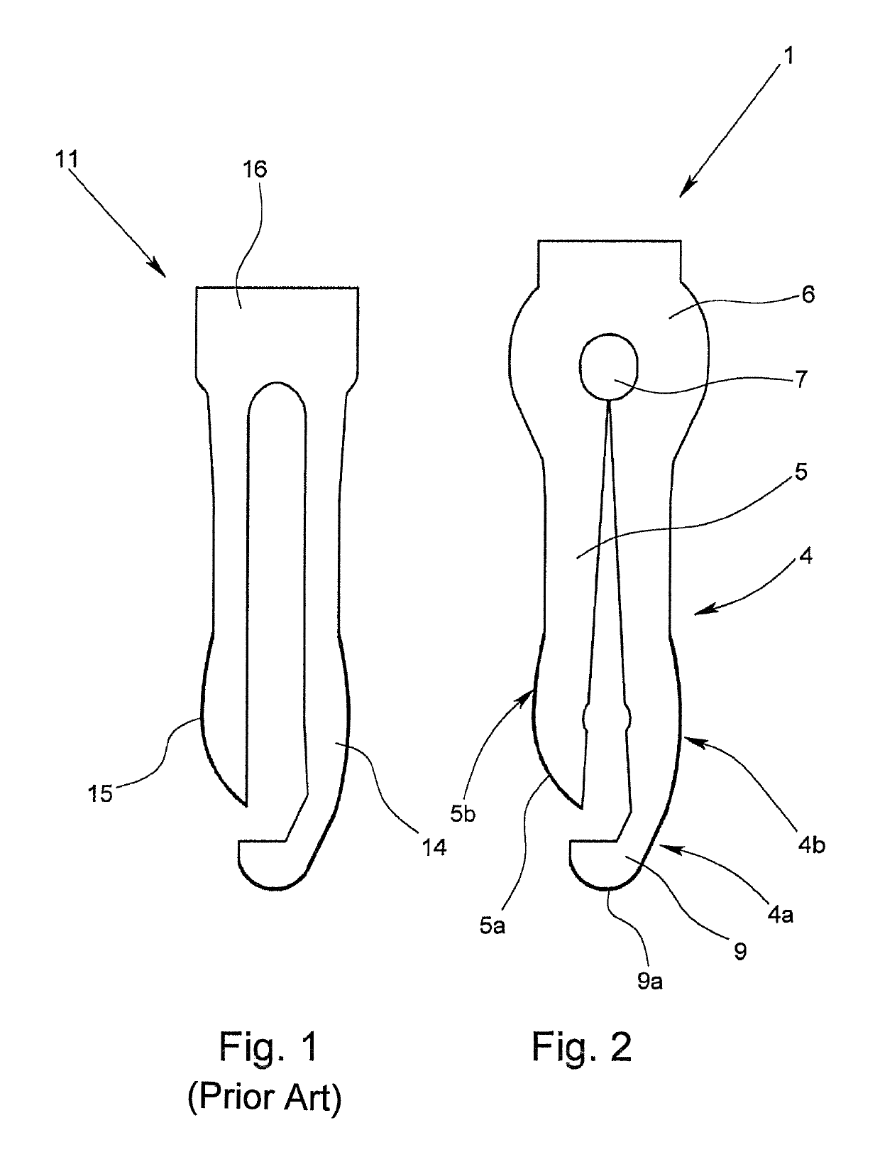
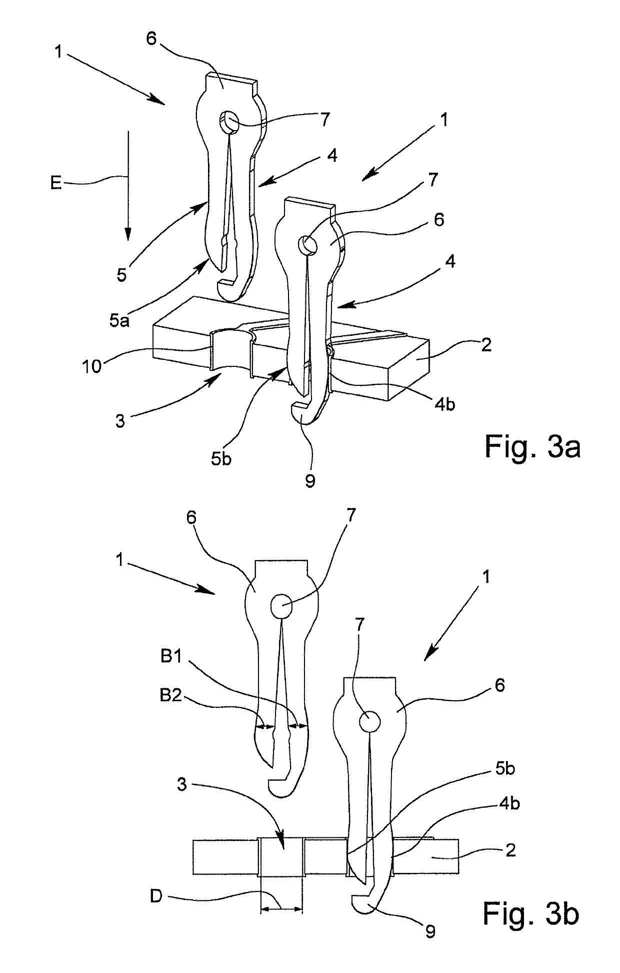
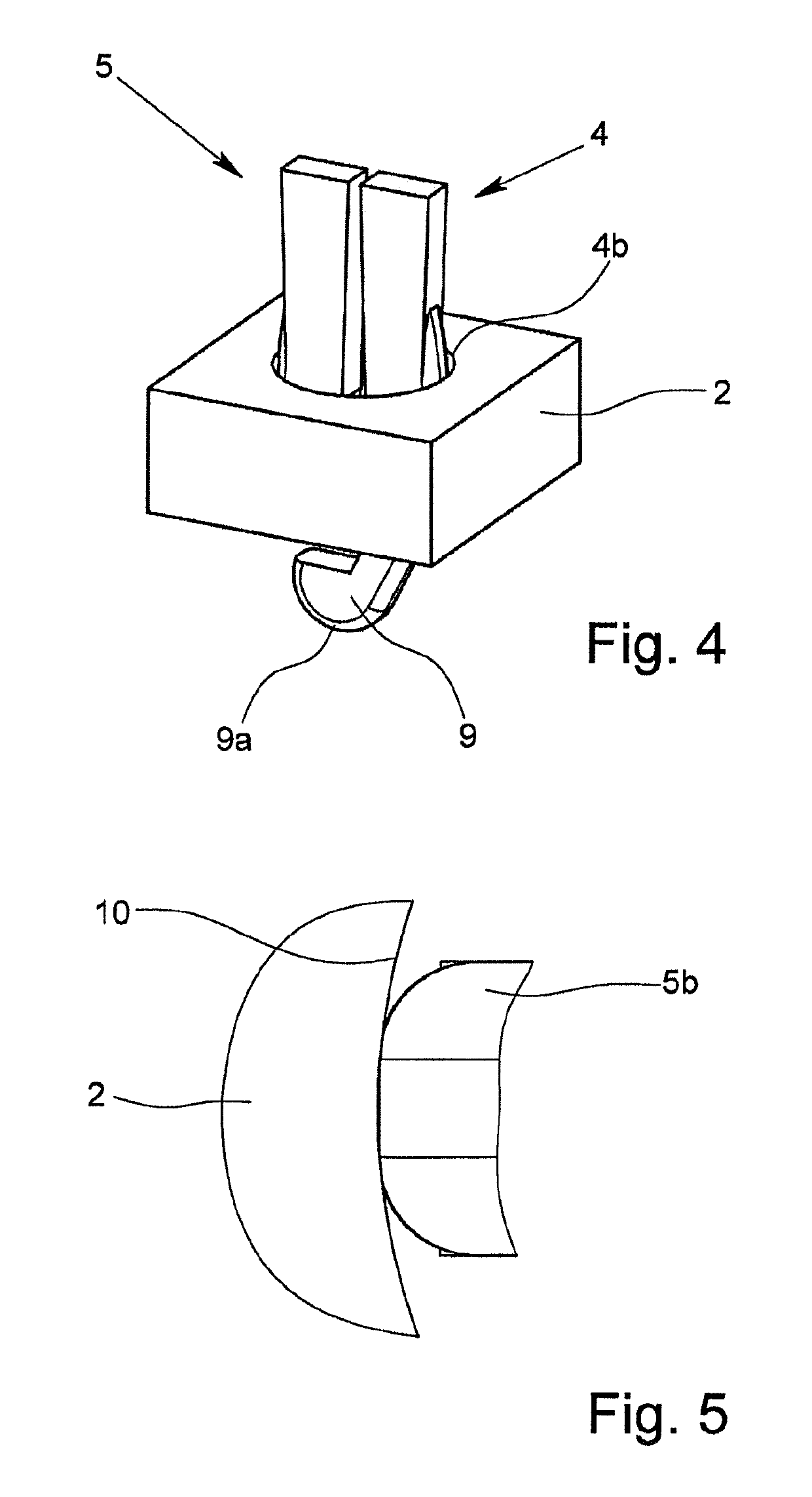
[0030]FIG. 1 shows a plug-in contact 11 according to the prior art which is punched out of a flat metal material. In comparison, FIG. 2 shows a plug-in contact 1 in accordance with the invention, the plug-in contact 1 in accordance with the invention also having been punched out of a flat metal material. Both plug-in contacts 1, 11 are used to make contact with the printed conductor of a circuit board 2 which is shown in FIG. 3 by way of a cutaway portion. A plug-in contact 1 is plugged into a corresponding contact hole 3 in the circuit board 2 for this purpose.

[0031]The known plug-in contact 11 which is shown in FIG. 1 has two contact legs 14, 15 which are connected to one another via a common connecting region 16, the contact legs 14, 15 extending out of the connecting region 16 in the plug-in direction E of the plug-in contact 11. In the known plug-in contact 11, the two contact legs 14, 15 are produced by the region between the contact legs 14, 15 being punched out when the plug...


PUM


Abstract

A plug contact for electrically contacting a circuit board by inserting the plug contact into a via hole in the circuit board, the plug contact having two flat contact arms that are resilient relative to each other, and a connecting region, from which the two contact arms extend in the plug-in direction of the plug contact, the plug contact being punched as a single piece from a flat metallic material. In the connection region, adjacent to the two contact arms, a recess is formed in the plug contact, the distance between the two contact arms increases from the recess towards the free ends of the contact arms, the two contact arms being spread apart relative to each other and the two contact arms together having a width which is the same as or only slightly smaller than the diameter of the corresponding via hole in the circuit board.

Description

BACKGROUND OF THE INVENTIONField of the Invention[0001]The invention relates to a plug-in contact for making electrical contact with a circuit board by means of plugging the plug-in contact into a contact hole of the circuit board, with two flat contact legs which are resilient relative to one another, and one connecting region from which the two contact legs extend in the plug-in direction of the plug-in contact, the plug-in contact being punched in one piece out of a metallic flat material. Moreover, the invention also relates to a method for producing a plug-in contact with two flat contact legs which are resilient relative to one another, and one connecting region.Description of Related Art[0002]Plug-in contacts for producing electrical and / or electronic connections between leads, different components or the like and busbars are known in different embodiments and for different applications. The plug-in contacts are plugged into corresponding receiving contacts or jack elements f...

Claims


Application Information

Patent Timeline
Patent Type & Authority Patents(United States)
IPC IPC(8): H01R13/05H01R12/58H01R43/16H01R12/71H05K1/18
CPCH01R12/71H01R12/585H01R13/052H01R43/16H05K1/184H05K2201/10878H05K2201/10901H05K2201/10939H05K2201/10863
Inventor GESKE, RALF
Owner PHOENIX CONTACT GMBH & CO KG
Features
  • R&D
  • Intellectual Property
  • Life Sciences
  • Materials
  • Tech Scout
  • Unparalleled Data Quality
  • Higher Quality Content
  • 60% Fewer Hallucinations
Learn More