Surgical instrument positioning system, apparatus and method of use as a noninvasive anatomical reference

a surgical instrument and positioning system technology, applied in the field of surgical instrument positioning system, can solve the problems of fractures, fractures, and other complications, and the placement of implants or the reduction of bone fragments may not be as close as desired by the user,

Active Publication Date: 2019-11-05
ORTHOGRID SYST HLDG LLC
View PDF24 Cites 0 Cited by
  • Summary
  • Abstract
  • Description
  • Claims
  • Application Information

AI Technical Summary

Benefits of technology

[0013]receive a digital image of a patient's anatomy adjusted for correct anatomical rotation with reference to a dimensioned pattern overlaid on the image of a patient's anatomy, the dimensioned pattern positioned on a primary alignment device; receive reference plane axis trackers data from a surgical device; receive reference plane axis trackers data from a primary alignment device; and compute a three-dimensional position of the surgical device, wherein one of the at least one processors is communicatively coupled to a display providing visual feedback regarding the three-dimensional position of the surgical device with respect to an anatomical feature.

Problems solved by technology

However, even with intraoperative fluoroscopic guidance, the placement of an implant or the reduction of a bone fragment may still not be as close as desired by the user.
For example, mal-positioning of the acetabular component during hip arthroplasty can lead to problems.
Unfortunately, the position of the patient's pelvis varies widely during surgery and from patient to patient.
Unfortunately, in a fracture scenario, the original anatomical position of these bone fragments has been compromised and their natural relationship with the correct anatomy is uncertain and requires the user to use his / her best judgment to promote a successful repair and subsequent positive outcome.
However, it has been suggested that the acetabulum may be deteriorated due to arthritis.
The invasiveness of these trackers is minimal but has been documented to lead to fractures and other complications, such as insertion site pain.
In addition, the set up is lengthy and adds considerable time to the surgery.
The accuracy of such system has not proved any additional benefit in surgical instrument and implant position.

Method used


Image

  • Surgical instrument positioning system, apparatus and method of use as a noninvasive anatomical reference
  • Surgical instrument positioning system, apparatus and method of use as a noninvasive anatomical reference
  • Surgical instrument positioning system, apparatus and method of use as a noninvasive anatomical reference

Examples


example 1

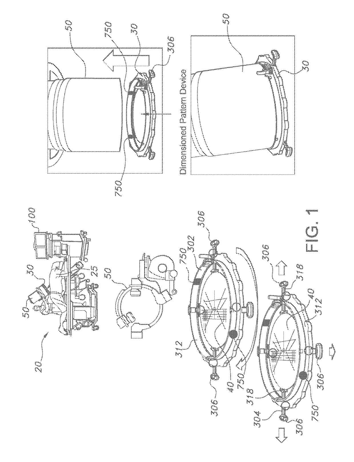
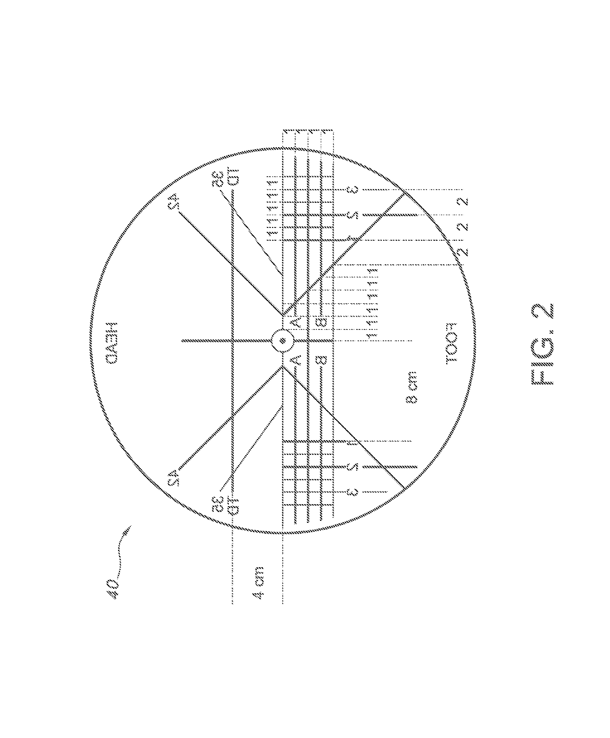
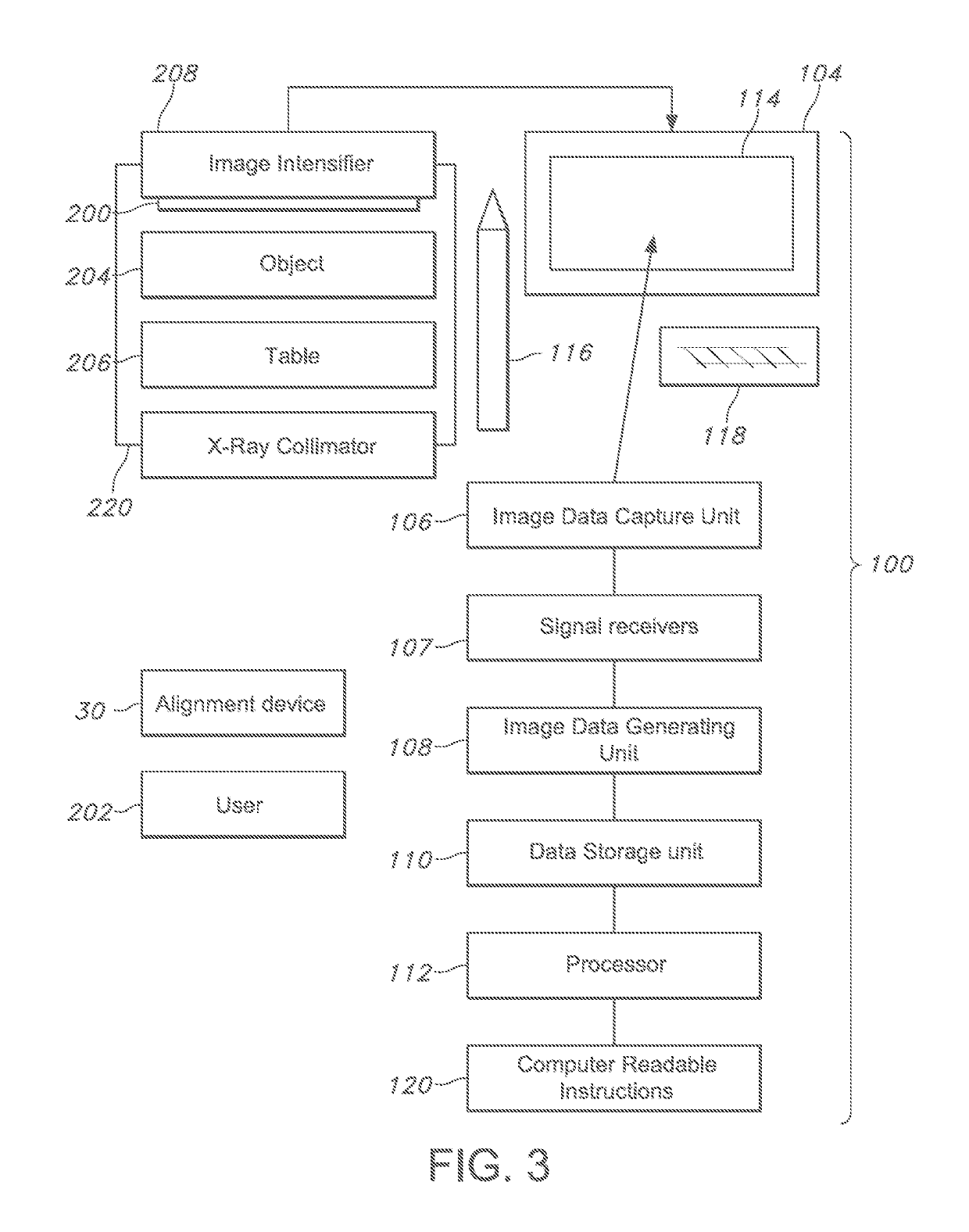
[0042]Now referring to FIGS. 7-9, an anatomical image, such as an X-ray image, of a patient 25 is acquired during a surgical procedure. Digital X-ray images are acquired intra-operatively, during surgical procedures such as joint replacements and trauma fracture reductions and deformity correction and implant placement / alignment. The acquired image can be viewed or further processed on a device, such as a computer with a monitor. A dimensioned radiopaque pattern 40 specific to the anatomical reference for a known surgical procedure is attached to a medical imaging device such as a fluoroscopic or portable radiographic machine. In another illustrative embodiment, the dimensioned pattern 40 is generated digitally on to the image. See U.S. Pat. Nos. 8,611,504, 9,456,874 and 9,610,134 hereby specifically incorporated by reference.

[0043]The intraoperative digital imaging allows immediate visualization of the bony anatomy of a patient 25. The skeleton's anatomical landmarks for reference ...


PUM


Abstract

The subject of this invention is a surgical instrument positioning system, method and apparatus, using an anatomical reference plane registered in a non-invasive manner and a method of intra-operative use of this instrument for joint replacements, spine, trauma fracture reductions and deformity correction and implant placement / alignment.

Description

CROSS REFERENCE TO RELATED APPLICATIONS[0001]This application is a § 371 National Stage Application of PCT / US17 / 40392 application filed Jun. 30, 2017 and U.S. provisional patent application Ser. No. 62 / 357,214 filed Jun. 30, 2016, under 35 U.S.C. § 111(a) (hereby specifically incorporated herein by reference).STATEMENT REGARDING FEDERALLY SPONSORED RESEARCH OR DEVELOPMENT[0002]None.REFERENCE TO SEQUENCE LISTING, A TABLE FOR A COMPUTER PROGRAM LISTING, COMPACT DISC APPENDIX[0003]None.FIELD OF THE INVENTION[0004]The subject of this invention is a surgical instrument positioning system, an apparatus using an anatomical reference plane registered in a non-invasive manner and a method of intra-operative use of this instrument for joint replacements, spine, trauma fracture reductions and deformity correction and implant placement / alignment.BACKGROUND OF THE INVENTION[0005]Many of the radiographic parameters essential to total hip arthroplasty (THA) component performance, such as wear and ...

Claims


Application Information

Patent Timeline
Patent Type & Authority Patents(United States)
IPC IPC(8): A61B34/20A61F2/46A61B17/70A61B17/56A61B90/00
CPCA61F2/46A61B17/7074A61B34/20A61B2090/3764A61B2017/564A61B2090/3966A61B2090/3983A61B5/062A61B5/066A61B5/067A61B2034/2048A61B2034/2051A61B2034/2065A61B2090/376
Inventor SAGET, EDOUARDBODDINGTON, RICHARDFRY, TAYLOR
Owner ORTHOGRID SYST HLDG LLC
Why Eureka
Try Eureka